A Concise Selection Guide for In-Line Polarizers

How do I select the right in-line polarizers? If you also have the same question in mind, then this guide will help you learn all those things that you should know for choosing the best in-line polarizers for your applications. But why do you need to buy only the best in-line polarizers? Why does their quality matter?

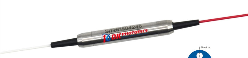
In-line polarizers are the small and compact fiber optic devices placed in line to improve and enhance the extinction characteristics of a fiber optic cable. They are designed to allow only one pre-defined polarization state and block the transmission of all other polarization states. Their use in many industries has become vital because if polarization extinction degrades in the fiber, it can lead to significant noise interference and reduce the performance of the entire fiber optic system.

Thus, one should never cut corners when buying in-line polarizers and should choose only the highest quality. So, without any delay, let’s find out how to buy the best in-line polarizers.

Things to Consider When Choosing the Best In-Line Polarizers

  • Polarization

It is no secret that light waves are highly susceptible to noise and interference, which is very harmful to the fiber optic systems’ performance and quality. Thus, to avoid unwanted interference and improve the performance of signals, in-line polarizers that have better control on the transfer of desired polarization state and block unwanted polarization states are considered the best choice. In short, it must transmit only linearly polarized light with a high extinction ratio and low insertion loss.

  • Signal Characteristics

The next thing you need to keep in mind includes signal characteristics. All fiber optic systems transmit light waves characterized by wavelength. Besides, a light signal is also characterized by the optical power of the signal, which is measured in dBm or mW. Due to the nature of the transport medium (i.e. fiber), fiber optic systems transmit usually longer light waves from red (650nm) to the infrared region. That’s why you see 650 nm in-line polarizers, 980nm in-line polarizers, etc. on the market.

Shorter wavelengths get perturbed due to scattering of the light source, and absorption bands at certain frequencies further attenuate the signal. Therefore, long wavelengths work better for fiber optic systems.

  • Optical Power

Optical power is the measure of wavelength and photon density. Usually, low-power signals are used in fiber optic systems. The most common units used for optical power are dBm or mW (milliwatts). A power level of 0 dBm is equivalent to 1mW, -10 dBm is 0.1 mW, and +10 dBm is equivalent to 10 mW.

  • Preferred Cable Type

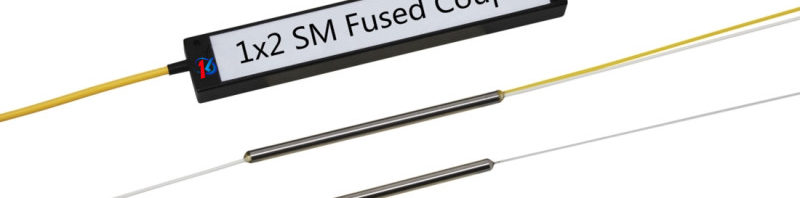
In fiber optics, there are two cable types: single mode optical fiber and multimode optical fiber. While single-mode fiber cable allows a single path for light, multimode fiber cable offers multiple paths for light. It is important to note that multimode fiber cables limit the distance that a signal can travel as multiple paths of transmission force the different modes of light to disperse, and hence, they also limit transmission bandwidth. On the other hand, single-mode fiber cables facilitate signal transmission at very high bandwidth and long transmission distances.

If you need high-quality 980nm in-line polarizers or in-line polarizers with other wavelength requirements, get in touch with DK Photonics.

What is a polarization maintaining filter coupler?

A polarization-maintaining filter coupler is an optical coupler that combines the light coming from the two input PM fibers into one output-PM fiber. This type of coupler supports the light wave of each polarization and doesn’t block any polarization. It also works as a splitter as it can also split the light typically into two ports. So, a PM filter coupler can work in both ways as a coupler and as a splitter.

It is basically designed to split high power linearly polarized light into multiple paths, without altering the state of polarization. You can also use it as a power tap for monitoring signal power flowing in a PM fiber system without affecting the linear SOP of the light traveling through the optical PM fiber.

 In a 1×2 PM filter coupler, the division of power occurs with a fixed proportion.

To suit the needs of different projects, there are various configurations available for polarization-maintaining filter couplers.

Different Configurations of PM Filter Couplers

The different configurations available for PM Filter couplers include but are not limited to:

  • 1×2 (one input/two outputs)
  • 2×2 (two inputs/two outputs)
  • 1×4 (one input/four outputs)
  • 2×3 (two inputs/three outputs)

How is the coupling ratio in PM Fiber couplers determined?

The coupling ratio of signals or splitting proportions depends on the PM Filter coupler’s configuration. A coupler ratio refers to the ratio in which input optical signals are divided between different outputs. For instance, with 50:50 coupling ratio in a 1×2 PM filter couplers, the optical signals are divided in equal proportion in two output-PM fibers. In such couplers, half of the input optical power is coupled to each port.

Other common coupling ratios include 90:10, 80:20, and 70:30. With these coupling ratios, a PM filter coupler doesn’t couple equal power to both the output-PM ports. For instance, in a PM filter coupling with an 80:20 coupling ratio, 80% percent of optical power is sent to one output PM fiber and 20 percent of the remaining optical power is directed to another output PM fiber.

Thus, you can easily design your optical fiber architecture as you have optical filter couplers with different configurations and can send optical power depending on whether you are sending it to the end-point or another device from where the optical power needs to be split further.

What should I know before choosing PM filter couplers?

First of all, you need to know the desired coupling ratio of PM filter couplers. Then, you need to check other parameters such as insertion losses, optical return loss (directivity), and excess loss. If an application involves differences in the polarization states, then you also need to analyze the polarization-dependent loss.

If you need polarization-maintaining filter couplers for applications such as PM fiber interferometers, power sharing in polarization-sensitive systems, signal monitoring in PM fiber systems, or fiber optic instruments, please get in touch with DK Photonics.  

What Are the Applications of Optical Fused Couplers?

People know that optical fused couplers are one of the important parts or elements of many fiber-optic setups. They even know that these couplers improve the efficiency of work and increase the overall productivity of the organization. But, the shocking part is that many of them don’t know the actual use of the optical fused couplers. They don’t know when and how to implement the features of optical fused couplers so that they get the most out of them. As a result, they only invest but get nothing in return. 

In this post, we will discuss a few common applications of optical fused couplers. If you think these applications are related to you, use the couplers accordingly. But before that, we would like to brief you about optical fused couplers. 

Basically, the optical fused couplers are defined with two different meanings. And these two meanings are applicable in different situations. 

First, the coupler acts as an optical fiber device with one or more input fibers and one or several output fibers. Light from an input fiber appears at one or more outputs with the power distribution potentially depending on the wavelength and polarization. 

Second, the coupler acts as a device for coupling or launching light from free space into a fiber. 

Generally, the first meaning of the optical fused couplers is considered. These couplers are fabricated in different ways such as two or more fibers are thermally tapered or fused so that their cores come into intimate contact over some length, use of side-polished fibers, and so on. 

Applications of optical fused couplers 

Cable TV system– The optical fiber couplers are used in a cable TV system in which they send the powerful signal from one transmitter to an optical fiber splitter. Thereafter, the splitter distributes the power over a large number of output fibers for different customers. 

Fiber interferometers– In different ways or for different things, the optical fused couplers are used in fiber interferometers. But, the common use is for optical coherence tomography or OCT. For this purpose, specially designed broadband couplers are preferred. 

Resonator of a fiber laser– A dichroic optical fused coupler is used within the resonator of a fiber laser to inject pump light. Another fiber coupler is used as the output coupler. Particularly, this technique is used in fiber ring lasers with no resonator ends where light could be injected. 

Fiber amplifiers and lasers– Even in fiber amplifiers and lasers, dichroic couplers are used. These couplers inject pump light or eliminate residual pump light from the signal output. 

High-power fiber lasers and amplifiers– Different from others, the multimode optical fused couplers are used in high-power fiber lasers and amplifiers. These couplers combine the radiation of several laser diodes and send them into the inner cladding of the active fiber or a double-clad fiber. 

These are just a few applications of optical fused couplers. To know more about their uses, you should connect with professionals and seek their help in their implementation in your organization. 

How does a Single Fiber CWDM Mux/Demux work?

Coarse Wavelength Division Multiplexing (CWDM) mux/demux is an important component in WDM systems, that is typically used to join multiple wavelengths onto a single fiber. Generally, bidirectional or dual-fiber CWDM mux/demux is used to transmit signals bi-directionally. It uses the same wavelengths for transmitting and receiving optical signals on both sides. However, bi-directional CWDM Mux/Demux is not the right choice for all applications. In some cases where there is only one wavelength or fiber available for signal transmission, you have to use single-fiber CWDM Mux/Demux.

In this post, you will learn about single-fiber CWDM Mux/Demux and how it works.

What does a single-fiber CWDM Mux/Demux mean?

Typically, a single-fiber CWDM Mux/Demux has only one simplex line port, which makes it different from a dual-fiber CWDM Mux/Demux design-wise. However, you can find some single-fiber CWDM Mux/Demux with duplex ports. Since it is a single-fiber CWDM Mux/Demux, only one port of the duplex port is used and the other is usually marked N/A.

A single-fiber CWDM Mux/Demux can also achieve dual-way transmission. In bidirectional CWDM networks, each wavelength runs in two opposite directions. On the other hand, each wavelength runs in only one direction in single-fiber CWDM Mux/Demux. But if one wants to create a dual-way transmission link between two different sites, one can use the same one wavelength over duplex fiber with dual-fiber CWDM Mux/Demux or use two wavelengths, i.e. one for the transmitter and the other for the receiver, over simplex fiber with single-fiber CWDM Mux/Demux.

How does a single-fiber CWDM Mux/Demux work?

In a CWDM network, there are 16 wavelengths that you can use to support 8 pairs of dual-way transmission. Let’s assume there are two sites, Site 1 and Site 2. An 8-channel single-fiber CWDM Mux/Demux is installed using 8 wavelengths for signal transmission and the other 8 wavelengths for receiving at Site 1. At Site 2, there is another single-fiber CWDM Mux/Demux installed. However, the wavelengths for transmission and receiving are reversed.

For example, a pair of dual-way optical signals is using 1270 nm wavelength for transmission and 1290 nm for receiving at Site 1, while, at Site 2, 1290nm is used for transmission and 1270 nm is used for receiving. That’s how, with single-fiber CWDM Mux/Demux, one can achieve dual-way transmission.

How do you find the right fiber optic transceivers for single-fiber CWDM Mux/Demux?

Since there are two different wavelengths on a duplex channel port, one can get easily confused while buying fiber optic transceivers for single-fiber CWDM Mux/Demux. The only thing you need to keep in mind is that the selection of fiber optic transceivers for single-fiber CWDM Mux/Demux mainly depends on the wavelength of transceiver/transmission. The fiber optic transceivers used for single-fiber CWDM Mux/Demux are different on the two sites.

All wavelengths in a single-fiber CWDM network go in one direction. For instance, SFP transceivers using 1470nm, 1510nm, 1550nm, and 1590nm are linked with the CWDM Mux/Demux onone side of the network. The SFP transceivers installed on the other side of the network are working on 1490nm, 1530nm, 1570nm, and 1610nm.

Thus, eight wavelengths are used for 4 pair dual-way transmission in a single-fiber CWDM network.

A Fundamental Guide to 2.0μm Single-Mode Fused Couplers

A 2.0μm single-mode fused coupler is an optical passive component designed to split off a portion of light for the purpose of optical monitoring and feedback. In this post, you will learn about the uses of 2.0μm single-mode fused couplers and a lot more.

What are the uses of 2.0μm single-mode fused couplers?

2.0μm single-mode fused couplers are immensely used in fiber amplifier power control and in transmission equipment for performance monitoring and feedback control.

Other important applications of 2.0μm single-mode fused couplers are EDFA, fiber laser, and testing instrumentations.

Apart from splitting optical signals between two fibers, 2.0μm single-mode fused couplers are also used to combine optical signals from two fibers into one fiber.

What is the significance of using fused fibers in an optical coupler?

A 2.0μm single-mode fused coupler is made of 2.0μm single-mode fiber in which only one type of light mode can propagate at a time. The term “fused” represents the construction of this coupler. It means the fiber used in it is designed by stretching, twisting, and fusing the two single-mode fibers so that their cores remain closer to each other.

The method used for fusion provides a simple, rugged, and compact construction to split and combine optical signals.

What is the difference between single-mode fused couplers and multimode fused couplers?

Multimode fused couplers are dependent on modes. In a multimode fused coupler, certain modes within one fiber can pass to the second fiber, while other modes don’t. It means the splitting ratio depends on which modes are excited within the fiber.

On the other hand, single-mode fused couplers transmit only one mode of light. Therefore, they don’t suffer from mode dependency. However, single-mode fused couplers are highly dependent on wavelength.

Even a difference in the wavelength of only 10nm can result in major changes in the splitting ratio in single-mode fused couplers.

Where can I buy 2.0μm single-mode fused couplers?

The 2.0μm Single-Mode Fused Couplers offered by DK Photonics are high-quality and highly reliable because they offer low levels of sensitivity to polarization. It enables them to more effectively monitor and manage optical networks. Besides, its 2.0μm single-mode fused couplers are known for offering low insertion loss, low polarization dependent loss, high stability, and excellent reliability.

At DK Photonics, you can buy 2.0μm Single-Mode Fused Couplers in a broad range of split ratios, lengths, and packaging and can also order these couplers with custom specifications.