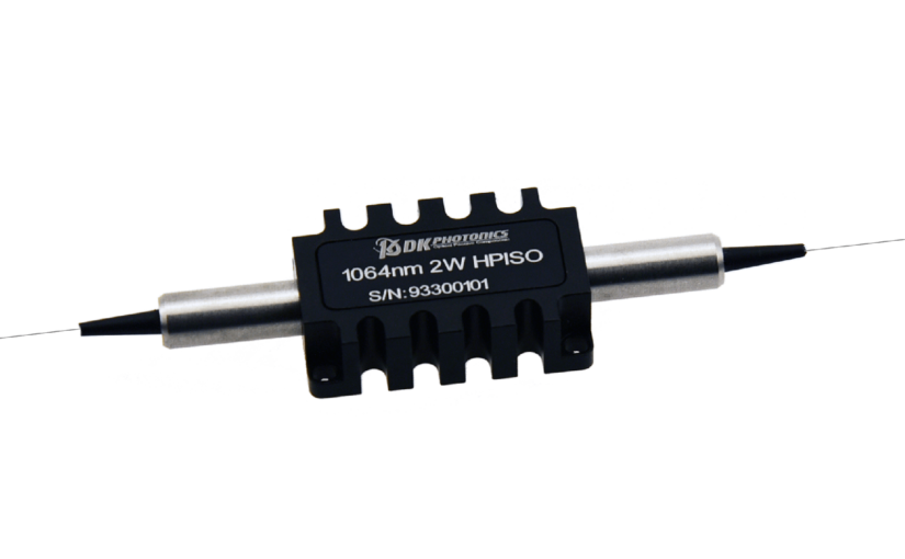
Understanding 1064nm High Power In line Optical Isolator -2W

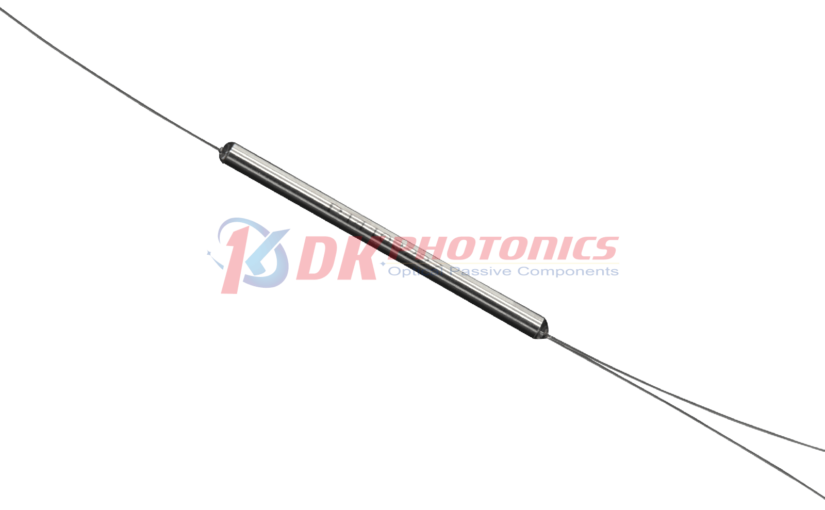
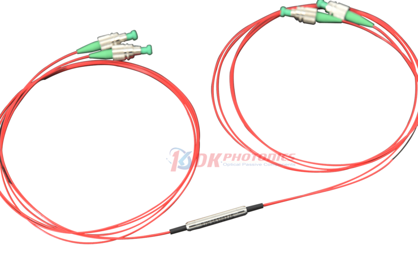
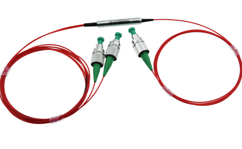
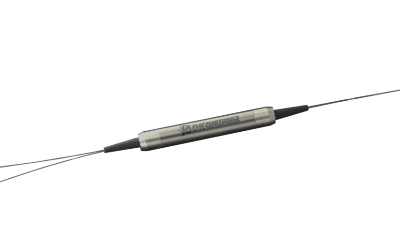
In fiber optics, getting things right is extremely important. Whether you’re working with fiber lasers, scientific instruments, or anything that needs high-power light transmission, having the proper components can make a huge difference. One such component is the 1064nm High Power In-line Optical Isolator -2W – a compact and powerful little device designed to ensure top performance in your fiber optic setups.

What exactly is this 1064nm High Power In-line Optical Isolator -2W thingy?

Simply put, it’s a device that lets light travel in one direction while blocking it from going backward. This feature is important for controlling unwanted reflections or feedback from messing with sensitive optical components like lasers or amplifiers.

While traditional isolators are made from TGG (Terbium Gallium Garnet) crystals, this one is constructed using Faraday crystals. Not only does this make it more compact, but it also allows it to handle higher power levels. It can operate within a wavelength range of ±5 nanometers around the central 1064nm wavelength, making it ideal for high-power fiber laser and instrumentation applications.

But What Makes This Isolator So Special?

Let’s break down its technical specs:

Central Wavelength:  It isdesigned to work at 1064 nanometers – a common wavelength for fiber lasers and instruments.

Wavelength Range: While centered at 1064nm, it can operate within ±5 nanometers, ensuring compatibility with various systems.

Isolation: This device offers up to 35 decibels (dB) of isolation, with a minimum of 28 dB within its operating range at 25°C. That’s high blocking power.

Insertion Loss: This refers to how much light is lost as it passes through the isolator. This device has a typical loss of 1.7 dB at 25°C, with a maximum of 2.0 dB at 25°C and 100 milliwatts (mW), 2.5 dB at 25°C and 1 watt (W), and 3.0 dB between 0°C and 50°C with 2W of power.

Polarization and Extinction: For single-mode fibers, the maximum polarization loss is 0.15 dB, ensuring minimal signal distortion. For polarization-maintaining fibers, the minimum extinction ratio is 18 dB (Type B) or 20 dB (Type F), ensuring efficient polarization maintenance.

Power Handling: This little device is a powerhouse. It can handle continuous wave (CW) powers of up to 1W or 2W, depending on the model. And for nanosecond pulses, it can withstand peak powers of up to 5 kW or 10 kW, making it perfect for pulsed applications.

Fiber Types: It is compatible with various fibers, including single-mode (e.g., 1060-XP, 10/125) and polarization-maintaining fibers (e.g., PM980-XP, PM1060L, PM 10/125 DC).

Temperature Range: It can operate between 0°C and 50°C, ensuring reliable performance in different environments.

With specs like these, it’s no wonder that 1064nm High Power In-line Optical Isolator -2W is a valuable component in high-power fiber optic applications across multiple industries:

Applications of 1064nm High Power In-line Optical Isolator -2W

Fiber Lasers:

These lasers are used in marking, cutting, welding, and material processing, depend on the high power handling and reflection prevention of the isolator for steady, effective operation.

Instrumentation:

In spectroscopy, interferometry, sensing, and other instrumentation setups, the isolator maintains signal integrity and prevents feedback for accurate, reliable measurements.

Telecommunications:

While designed for high power, isolators also prevent reflections and maintain signal quality over long fiber optic links.

Scientific Research:

High-power lasers and sensitive components in labs benefit from the isolator’s protection and reliable data collection.

Medical Applications:

In laser surgery, therapy, and other medical procedures involving high-power lasers, the isolator enhances safety and effectiveness by preventing back-reflections.

No matter the application, the 1064nm High Power In-line Optical Isolator -2W is a versatile component that can boost the performance and reliability of your fiber optic systems.

This compact and high-performance isolator offers exceptional isolation, high power handling, and compatibility with various fiber types. If you’re working with fiber lasers, instruments, or any application requiring precise optical transmission, this isolator is a must-have addition to your toolkit. With its robust design and extensive technical capabilities, it ensures optimal performance and reliability, even in the most demanding environments.
High Power Polarization Beam Combiner/Splitter: A Comprehensive Guide

Polarization beam combiners/splitters are fascinating devices used in optics and telecommunications. In this blog, we’ll delve into the world of High Power Polarization Beam Combiner/Splitter, shedding light on what they are, how they work, and their applications without getting too technical.

What is a High Power Polarization Beam Combiner/Splitter?

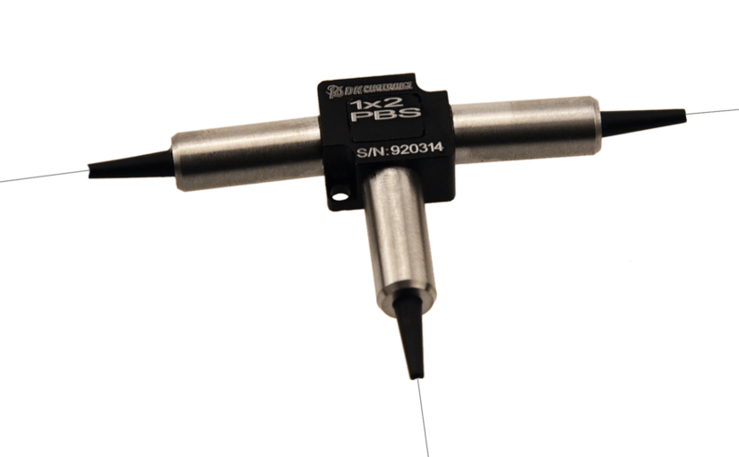
  1. Introduction: A High Power Polarization Beam Combiner/Splitter is a specialized optical component used to manipulate light waves based on their polarization.
  2. Functionality: It combines or splits light beams from input fibers, effectively managing the polarization of light.

How Does it Work?

  1. Combining Light: When used as a combiner, it merges light beams from two polarization-maintaining (PM) input fibers into a single output fiber.
  2. Splitting Light: As a splitter, it divides light from an input fiber into two output fibers based on their polarization.

Applications

  1. Telecommunications: In the telecom industry, these devices are crucial for managing and manipulating light signals efficiently.
  2. Optics Research: High Power Polarization Beam Combiner/Splitters are also indispensable in optical research for various experiments and studies.

Advantages

  1. Efficiency: They offer high power handling capabilities, making them suitable for demanding applications where power levels are crucial.
  2. Versatility: These devices are versatile and can be tailored to specific requirements, providing flexibility in different setups.

Conclusion

High Power Polarization Beam Combiner/Splitters are vital components in optics and telecommunications, facilitating the manipulation and management of light waves with precision and efficiency. Whether it’s combining or splitting light beams, these devices play a crucial role in various applications, from telecommunications infrastructure to advanced optical research. With their high power handling capabilities and versatility, they continue to be indispensable tools for researchers and engineers pushing the boundaries of light-based technologies.

Key Components of a Polarization Maintaining Fused WDM System

Have you ever wondered how the internet works? It’s like a big network of roads where information travels from one place to another. But did you know that there are special tools called Polarization Maintaining Fused WDM that help make this network strong and reliable? Let’s learn about the key components of a Polarization Maintaining Fused WDM system in simple words!

1. Optical Fibers

Imagine optical fibers like tiny, invisible roads that carry beams of light. These fibers are the backbone of a Polarization Maintaining Fused WDM system. They help guide the light signals from one place to another without getting lost or mixed up.

2. Wavelength Division Multiplexers (WDMs)

Wavelength Division Multiplexers, or WDMs for short, are like traffic controllers on the optical fiber roads. They help manage the flow of light signals by splitting them into different wavelengths, or colors, so they can travel together without crashing into each other.

3. Polarization Maintaining Fiber (PMF)

Polarization Maintaining Fiber is a special type of optical fiber that keeps the light signals aligned in a specific direction. It’s like having lanes on a road where cars can only travel in one direction. This helps prevent the light signals from getting mixed up or scattered along the way.

4. Fused WDM Devices

Fused WDM Devices are the heart of a Polarization Maintaining Fused WDM system. These devices combine the functions of WDMs and PMFs to efficiently manage and guide the light signals. They ensure that the signals stay organized and reach their destination safely and without any interference.

5. Connectors and Couplers

Connectors and Couplers are like the bridges and tunnels on the optical fiber roads. They help connect different parts of the Polarization Maintaining Fused WDM system together, allowing the light signals to travel smoothly from one component to another.

Why Polarization Maintaining Fused WDM Matters

Polarization Maintaining Fused WDM matters because it helps make the internet faster, more reliable, and less prone to errors. By keeping light signals aligned and organized, Polarization Maintaining Fused WDM ensures that data travels quickly and accurately through optical networks.

Fewer delays, less data loss, and better overall performance for internet users can be achieved. Additionally, Polarization Maintaining Fused WDM systems allow for efficient use of optical fibers, maximizing the capacity of communication networks and enabling seamless connectivity for millions of people worldwide.

The major components of a Polarization Maintaining Fused WDM system function like a well-oiled machine to keep the internet working smoothly. From optical fibers and WDMs to Polarization Maintaining Fiber and Fused WDM devices, each component plays an important role in directing and managing the flow of light data.

What Factors Affect the Performance of Polarization Maintaining Tap Couplers?

A Polarization Maintaining Tap Coupler is a special device used in fiber optic systems. It helps split or combine light signals while making sure the light stays in its original state, called polarization. But there are several things that can make a Polarization Maintaining Tap Coupler work better or worse. What are these factors that affect the performance of polarization maintaining tap couplers? Let’s take a look at seven of these important factors.

But before we begin, let us look at how these Polarization Maintaining Tap Couplers work.

How Do Polarization Maintaining Tap Couplers Work?

Polarization Maintaining Tap Couplers are made up of special fibers that have a unique structure that allows them to maintain the polarization of the light passing through them.

When light enters the coupler, it is split or combined while preserving its polarization state. This is important for applications where the polarization of the light signal needs to be maintained, such as in fiber optic sensors or specialized communication systems.

The Type of Fiber Used

Polarization Maintaining Tap Couplers are made with special fibers that can keep the light in its polarized state. If the fiber isn’t the right type or if it’s not of good quality, the coupler might not be able to keep the light polarized properly.

How It Is Manufactured

Polarization Maintaining Tap Couplers are carefully put together using special techniques. If there are any mistakes or problems during the making process, it can cause issues like too much light being lost or the polarization not being maintained well.

How Much Light It Splits or Combines

The coupler needs to split or combine the right amount of light for what it’s being used for. If it’s splitting or combining too much or too little light, it won’t work as well as it should.

The Environment Around It

Factors like temperature, humidity, and vibrations can affect how well a Polarization Maintaining Tap Coupler works. Very hot or cold temperatures, or too much moisture in the air, can make the fibers inside the coupler change shape a little bit, which can mess up the polarization. Vibrations can also cause problems.

How It Is Packaged or Protected

The way the Polarization Maintaining Tap Coupler is packaged and protected can also make a difference. If the packaging isn’t good enough, it might not protect the coupler from factors like temperature changes or vibrations, which can make it not work as well.

How It Is Connected to Other Parts

In many fiber optic systems, the Polarization Maintaining Tap Coupler needs to be connected to other parts. If these connections aren’t done correctly, it can cause problems like the fibers getting misaligned or stressed, which can affect how well the coupler maintains polarization and sends light.

The Coupling Ratio

The coupling ratio is how much light the coupler splits or combines. Different uses might need different coupling ratios. If the ratio isn’t right for what the coupler is being used for, it might not work as well as it should.

In order to ensure that Polarization Maintaining Tap Couplers function as best they can, engineers and technicians should try to understand these seven important factors. They can choose the right fibers, make the couplers carefully, pick the right coupling ratio, protect them from factors  like temperature changes and vibrations, package them properly, connect them correctly, and more.

How to Maximize Performance with Polarization Maintaining Filter Couplers

In the world of fiber optic communications, maintaining the polarization of light signals is important for ensuring reliable data transmission and efficient signal processing. This is where Polarization Maintaining Filter Couplers (PMFCs) play a pivotal role.

Due to their ability to maintain light’s polarization state, these specialized optical components offer improved stability and performance in a range of photonic applications.

Understanding Polarization Maintenance

The term “polarization” describes how an electric field is oriented within a light wave. In a fiber optic system, the polarization of the light can easily become scrambled or distorted due to various environmental factors, such as bending, twisting, or temperature fluctuations. This polarization instability can lead to signal degradation, reduced efficiency, and even data loss.

Polarization Maintaining Filter Couplers are engineered to mitigate these challenges by maintaining the polarization state of the light as it travels through the optical system. PMFCs maximize the overall performance of the fiber optic network by maintaining the polarization, which guarantees that the light propagates in a consistent and predictable manner.

Key Factors for Maximizing PMFC Performance

To maximize the performance and stability of Polarization Maintaining Filter Couplers, there are several important factors to consider:

Precise Alignment

Proper alignment of the PMFC is crucial for ensuring optimal polarization maintenance. The input and output fibers must be precisely aligned to ensure that the light beam is coupled efficiently, without introducing any unwanted polarization changes.

Careful Design and Construction

The internal structure and materials used in the PMFC design play a significant role in its ability to maintain polarization. Manufacturers must carefully engineer the coupler’s components, such as the waveguide and coupling region, to minimize polarization-induced losses and maintain a stable polarization state.

Environmental Stability

Polarization Maintaining Filter Couplers must be able to withstand various environmental conditions, such as temperature fluctuations, mechanical stress, and vibrations, without compromising their performance. Robust construction and the use of materials with low thermal expansion coefficients can help ensure the PMFC’s stability under varying environmental conditions.

Wavelength Dependence

The performance of a PMFC can be influenced by the wavelength of the light being transmitted. Manufacturers often design PMFCs to operate optimally within a specific wavelength range, ensuring consistent polarization maintenance across the desired spectrum.

Careful Handling and Installation

Even the most well-designed Polarization Maintaining Filter Coupler can experience performance degradation if it is not handled and installed properly. Careful attention must be paid to minimizing mechanical stress, avoiding contamination, and ensuring secure mounting to maintain the coupler’s polarization-preserving capabilities.

By addressing these key factors, users can maximize the performance and stability of Polarization Maintaining Filter Couplers in their fiber optic systems.

Furthermore, advancements in PMFC design, manufacturing, and testing techniques continue to push the boundaries of what these optical components can achieve. As the demand for high-performance, polarization-sensitive photonic devices grows, the importance of Polarization Maintaining Filter Couplers  will only continue to increase.

Use of 2.0μm Single-Mode Fused Couplers in Fiber Optic Systems

Data travels at the speed of light in the world of fiber optics and every component plays an important role in making sure that the communication is efficient and reliable. The single-mode fused coupler is one such important component. When talking about single-mode couplers, 2.0μm single-mode fused couplers are an effective single-mode coupler used in optic fibers.

Today, we’re going to explore the advantages of using 2.0μm single-mode fused couplers in fiber optic systems. But first, let’s understand what a single-mode fused coupler is.

Understanding Single-mode Fused Couplers

Imagine a device that can split or combine optical signals traveling through fiber optic cables. That’s what a single-mode fused coupler does. It’s a small, yet powerful, device that can take a single input signal and divide it into two or more output signals, or it can combine multiple input signals into a single output.

Now, how does this work in a fiber optic system?

Imagine you have a fiber optic cable that’s carrying data, and you need to access that data at multiple points along the way. That’s where the single-mode fused coupler comes in. It can be installed in the fiber optic cable, and it will allow you to tap into the signal without interrupting the main data flow. This is incredibly useful for functions such as monitoring the network, splitting the signal for different purposes, or even adding new connections to the system.

But why use a 2.0μm single-mode fused coupler, especially? Let’s explore the five key advantages:

5 Main Advantages of 2.0μm single-mode fused coupler

1. Improved Performance

The 2.0μm wavelength range offers superior performance compared to the traditional telecom wavelengths. Therefore, it results in higher data transmission rates, lower signal loss, and better overall efficiency in your fiber optic system.

2. Reduced Attenuation

One of the biggest challenges in fiber optic systems is signal attenuation, where the signal weakens as it travels through the cable. The 2.0μm wavelength has significantly lower attenuation, which means the signal can travel much farther without needing to be amplified or repeated.

3. Enhanced Stability

The 2.0μm single-mode fused coupler is designed with exceptional stability in mind. This device provides reliable and consistent operation even in challenging environments like fluctuations in temperature and vibrations.

4. Increased Bandwidth

The 2.0μm wavelength range offers a wider bandwidth compared to traditional telecom wavelengths. This device is considered ideal for applications that require high-bandwidth communication because of its ability to transfer more data at faster speeds.

5. Compatibility with Emerging Technologies

As technology continues to evolve, the 2.0μm wavelength range is becoming increasingly important. Many cutting-edge laser systems and advanced research applications are leveraging this wavelength, and the 2.0μm single-mode fused coupler is perfectly suited to integrate with these new technologies.

Whether you’re a network administrator, a telecommunications engineer, or someone who appreciates the power of modern communication technology, the 2.0μm single-mode fused coupler is definitely worth considering for your fiber optic needs.

Polarization Insensitive Optical Circulators: How they Work and what is Their Importance 

As you delve into the area of optical communications, you’ll come up with an incredible tool that has revolutionized the way indicators traverse fiber-optic networks – the polarization-insensitive optical circulator. This unassuming but imaginative component performs a pivotal role in ensuring efficient and dependable signal transmission, making it a necessary component in modern optical systems. 

The Principle behind polarization-insensitive optical Circulators 

At the heart of an optical circulator lies a clever association of optical components that control the flow of light signals. These gadgets typically feature three or more ports, with every port serving a different function. Light getting into one port is directed to the next port in a particular circular pattern, taking into consideration the separation of incoming and outgoing signals. 

The actual magic, however, lies in the polarization-insensitive nature of these circulators. Conventional circulators have been sensitive to the polarization state of the incoming light, leading to signal losses and degradation. Polarization-insensitive optical circulators, however, function efficiently irrespective of the polarization of the input sign, ensuring the most optimal overall performance and minimizing signal distortion. 

Applications and Importance 

Polarization-insensitive optical circulators find several applications in fiber-optic communication systems, making them invaluable additions in today’s interconnected world. 

  • Bidirectional Communication: One of the primary uses of optical circulators is to facilitate bidirectional communication over a single fiber. By setting apart the incoming and outgoing signals, these gadgets allow efficient -manner communication, maximizing the capacity of existing fiber infrastructure. 
  • Optical Amplification: In long-haul fiber-optic networks, optical amplifiers are incorporated to reinforce the signal strength over full-size distances. Polarization-insensitive optical circulators play a crucial function in routing the amplified signal back into the fiber while avoiding unwanted reflections, ensuring optimal signal quality. 
  • Optical Monitoring and Testing: Optical circulators discover applications in monitoring and testing fiber-optic structures. By diverting a small portion of the signal to a designated port, these gadgets permit real-time monitoring of signal quality and power levels, facilitating proactive maintenance and troubleshooting. 

The Technological gain 

Polarization-insensitive optical circulators provide several technological advantages over their traditional counterparts: 

  • Improved performance: By disposing of polarization-based losses, these circulators ensure consistent and reliable signal transmission, lowering the want for complex compensation techniques. 
  • Versatility: With their potential to deal with signals of any polarization state, polarization-insensitive optical circulators can be seamlessly integrated right into an extensive range of optical systems, simplifying design and deployment. 
  • Cost-Effectiveness: By minimizing signal losses and maximizing the efficiency of existing fiber infrastructure, these circulators contribute to the overall cost-effectiveness of optical communication networks. 

As the demand for high-speed, dependable, and efficient optical communication systems continues growing, polarization-insensitive optical circulators will undoubtedly play an increasingly critical role. Their capacity to conquer polarization-associated challenges and ensure optimal signal transmission makes them a vital aspect in the ever-evolving landscape of fiber-optic technology. 

Understanding Pump and Signal Combiners

In the world of fiber optics, the efficiency and performance of optical systems rely heavily on components like pumps and signal combiners. These devices play a crucial role in combining multiple optical signals or pumps into a single output, simplifying optical setups and enhancing overall system performance.

What is a Pump and Signal Combiner?

A pump and signal combiner is a specialized optical component used in various fiber optic applications, particularly in fiber lasers and amplifiers. It’s designed to combine high-power pump lasers with low-power signal lasers into a single optical fiber, enabling efficient energy transfer and amplification.

How Does It Work?

  1. Combining Signals: The combiner merges pump signals, which provide the energy required for amplification, with weaker signal inputs, such as data signals, into a single optical path.
  2. Efficient Energy Transfer: By combining the signals, the combiner ensures that the pump energy efficiently transfers to the signal, enabling effective amplification without significant losses.
  3. Enhanced System Performance: With all signals merged into one fiber, the system becomes more compact, simpler, and easier to manage, leading to improved overall performance.

Applications

  1. Fiber Lasers: Pump and signal combiners are integral components in high-power fiber lasers, where they combine pump lasers with signal lasers to achieve efficient amplification and laser output.
  2. Fiber Amplifiers: In optical fiber amplifiers, these combiners play a crucial role in combining multiple pump sources with signal inputs for effective signal amplification.
  3. Telecommunications: They are also used in telecommunications networks for signal amplification and transmission over long distances.

Advantages

  1. Simplicity: By combining multiple signals into one fiber, the system design becomes simpler and more compact.
  2. Efficiency: Pump and signal combiners ensure efficient energy transfer between pump and signal sources, maximizing system performance.
  3. Cost-Effectiveness: They contribute to cost savings by reducing the need for additional optical components and simplifying system maintenance.

In conclusion, pump and signal combiners are essential components in fiber optic systems, enabling efficient energy transfer and amplification of optical signals. Their role in simplifying system design, enhancing performance, and reducing costs makes them indispensable in various applications across industries.

Demystifying DWDM Mux/Demux for Seamless Communication

In the world of optical fiber communication, DWDM Mux/Demux technology plays a crucial role in maximizing the capacity and efficiency of data transmission. Let’s delve into what DWDM Mux/Demux is and how it revolutionizes telecommunications.

What is DWDM Mux/Demux?

DWDM stands for Dense Wavelength Division Multiplexing. It’s a technology used to combine multiple optical signals onto a single optical fiber by using different wavelengths of light. Mux/Demux, short for Multiplexer/Demultiplexer, are key components of DWDM systems.

Multiplexer (Mux):

The Mux part of DWDM technology combines multiple optical signals from different sources onto a single optical fiber. Each signal is assigned a specific wavelength, allowing them to coexist without interfering with each other.

Demultiplexer (Demux):

On the receiving end, the Demux separates the combined signals back into their original wavelengths, allowing each signal to be directed to its intended destination.

How Does DWDM Mux/Demux Work?

  1. Wavelength Separation: Each input signal is assigned a specific wavelength of light.
  2. Combining Signals: The Multiplexer combines these signals onto a single fiber by utilizing the unique properties of each wavelength.
  3. Transmission: The combined signals travel through the fiber optic network.
  4. Demultiplexing: At the receiving end, the Demultiplexer separates the signals based on their wavelengths.
  5. Routing Signals: Each demultiplexed signal is then directed to its designated destination.

Benefits of DWDM Mux/Demux:

  1. Increased Capacity: By utilizing different wavelengths, DWDM significantly increases the capacity of optical fiber networks.
  2. Efficiency: It allows multiple signals to be transmitted simultaneously, optimizing bandwidth usage.
  3. Cost-Effectiveness: DWDM reduces the need for additional fibers, saving on infrastructure costs.
  4. Long-Distance Transmission: It enables data transmission over longer distances without signal degradation.

Applications of DWDM Mux/Demux:

  1. Telecommunications: Used in long-haul and metro networks for high-speed data transmission.
  2. Internet Backbone: Backbone networks utilize DWDM to handle large volumes of data traffic.
  3. Data Centers: Enables efficient connectivity between servers and storage devices.

In conclusion, DWDM Mux/Demux technology is a cornerstone of modern telecommunications, enabling high-capacity, efficient, and cost-effective data transmission over optical fiber networks.

CWDM Mux/Demux: Simplifying Fiber Optic Communication

Optical fiber communication has revolutionized the way data is transmitted over long distances, enabling high-speed internet, telecommunication, and more. Among the many components involved, CWDM Mux/Demux plays a crucial role in maximizing the efficiency of optical networks. Let’s delve into what CWDM Mux/Demux is and how it works:

What is CWDM Mux/Demux?

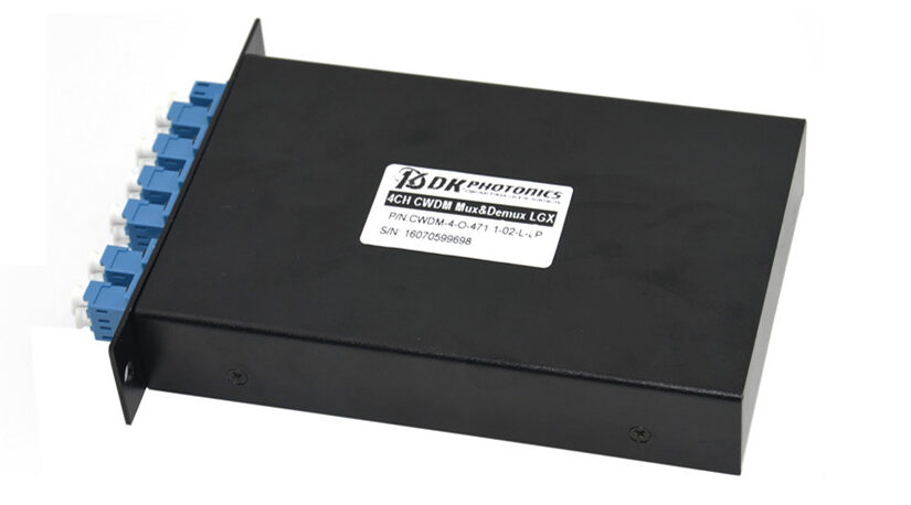
CWDM stands for Coarse Wavelength Division Multiplexing. CWDM Mux/Demux is a passive optical component used in fiber optic communication networks to combine multiple optical signals of different wavelengths onto a single fiber or to separate these signals back into individual wavelengths.

How Does CWDM Mux/Demux Work?

CWDM Mux/Demux operates based on the principle of wavelength division multiplexing (WDM). It consists of multiple input and output ports, each corresponding to a specific wavelength channel. The Mux (Multiplexer) combines several incoming optical signals with different wavelengths into a single fiber, while the Demux (Demultiplexer) separates these signals back into individual channels at the receiving end.

Benefits of CWDM Mux/Demux:

  • Increased Bandwidth: By utilizing different wavelengths, CWDM Mux/Demux allows for the simultaneous transmission of multiple data streams over a single fiber, effectively increasing the bandwidth capacity of the network.
  • Cost-Effective Solution: CWDM technology is more cost-effective compared to Dense Wavelength Division Multiplexing (DWDM), making it ideal for applications where high channel counts are not required.
  • Simplified Network Architecture: CWDM Mux/Demux simplifies network architecture by reducing the number of fibers needed for transmission, thus minimizing installation complexity and maintenance costs.

Applications of CWDM Mux/Demux:

  • Telecommunication: CWDM technology is widely used in telecommunication networks to increase the capacity and efficiency of data transmission.
  • Enterprise Networks: It is employed in enterprise networks for connecting multiple locations and data centers.
  • Broadcasting: CWDM Mux/Demux facilitates the transmission of high-definition video and audio signals in broadcasting applications.

In conclusion, CWDM Mux/Demux plays a crucial role in optimizing optical fiber communication networks by enabling the efficient multiplexing and demultiplexing of optical signals. Its cost-effectiveness and simplicity make it a preferred choice for various applications requiring increased bandwidth and streamlined network architecture.