How can high-power circulators increase network capacity?

As the demand for fiber optics networks is rapidly growing, more businesses and network service providers are looking for ways to increase the capacity of their networks. One traditional way to increase the capacity of a fiber network is to install more optical fiber cables. However, this can be extremely expensive and thus, limits the ability to cater to the increasing demand for more data and bandwidth.

However, the ongoing research and development in optical passive components have now made it possible to double the network capacity without installing additional optical fibers. The one small component that has made it possible to double the capacity of a fiber network is a high-power circulator.

What are high-power circulators?

High-power circulators are non-reciprocal optical passive components that route incoming optical signals from one port to the next port while blocking transmission from one port to the previous port. It can handle high levels of optical power and is specifically designed for high-power applications, including communication, fiber lasers, etc.

Some examples of high-power circulators are:

  • 100W 1064nm high-power circulators
  • 30W 1550nm high-power PM circulators
  • 10W 2000nm 3-port high-power PM optical circulator s

How do high-power circulators increase network capacity?

The use of high-power circulators provides the ease and convenience of doubling the transmission capacity of a fiber optic network without requiring optical fiber cables. High-power optical circulators are three-port, non-reciprocating, and unidirectional devices that help you achieve bidirectional propagation of light signals in a single fiber. Besides, they also result in obtaining low insertion loss and low crosstalk between two channels.

Typically, bidirectional optical links can be operated in full-duplex or half-duplex mode. In full-duplex, optical signals can be sent and received simultaneously. On the other hand, in half duplex mode, optical signals can be either sent or received but not both at the same time. A half-duplex transmission can be achieved by using either single or double fibers and a full-duplex transmission is implemented by using two fibers.

However, by using high-power circulators, bidirectional transmission can be done through a single fiber, thus, minimizing the amount of optical fiber needed and maximizing the transmission of optical signals over a single fiber.

As a result, it also helps eliminate the need for more powerful transmitters, more sensitive receivers, and more optical amplifiers, making the whole fiber network more economical. The cost is further reduced because high-power circulators can be obtained at cheaper prices.

To increase the isolation and extinction ratio of optical circulators, birefringent crystals, such as Terbium Gallium Garnet (TGG), are used to design these components.

Multi-port high-power circulators, such as 3-port high-power circulators, act as a roundabout for light where each input port is routed to exactly one output port in a non-reciprocal fashion. As a result, integrated circulators can double the network capacity in many data centers and telecommunication networks.

At DK Photonics, you can buy a wide range of high-power circulators, such as TTG-based 1064nm high-power circulators, 1030nm high-power circulators, 1080nm high-power circulators, and more. If you don’t find the specifications you need for high-power circulators for your application, please feel free to contact us.

Are 1064nm High Power Isolators are TGG-Based or Faraday-Based?

The 1064nm high-power isolators are small optical passive components that permit the light to travel in one direction only, operate at 1064nm wavelength, and are widely used in high-power fiber laser and amplifier applications. They help prevent any reflected light from going back to the source and hence, reduce feedback problems. These optical isolators are specifically designed to handle high power and hence, many high-power isolators can handle even a hundred Watts. On the other hand, low-power isolators can work with only 0.5 or 1 to 5 Watts.

Do high-power isolators use TGG or Faraday materials?

While some high-power isolators contain TGG crystals, others may have alternative Faraday materials. Take note that TGG crystals are also a type of Faraday material and they are the most common crystals used for optical isolators. Let’s find out what using TGG crystals and alternative Faraday materials means for high-power isolators.

What is TGG?

TGG stands for Terbium Gallium Garnet (Tb3Ga5O12). It is the most commonly used single-crystal Faraday rotator for optical isolator applications. Since TGG can melt congruently under the temperature of ~1825 degrees Celsius, large crystals of TGG can be easily made using the Czochralski technique. While one can easily grow these crystals in large sizes, bulk defects do not allow for fully utilizing these crystals. Some of these defects include color centers, dislocations, strain areas, etc.

TGG is widely used in 1064nm high-power isolators but it is very sensitive to increase absorption at this wavelength. Typical values for absorption at 1064nm for TGG range from 0.20 to 0.30%/cm.

What are Alternative Faraday Materials to TGG?

Since there are intrinsic limitations in the performance of TGG crystals, alternative Faraday materials are being explored and researched for delivering higher performance. The two great examples of alternative Faraday materials include lithium terbium fluoride (TLF) (LiTbF4) and potassium terbium fluoride (KTF) (KTb3F10).

These are small crystals that possess small non-linear refractive indices and thermo-optic coefficients, while also exhibiting Verdet constants similar to or near to those of TGG crystals. Hence, TLF and KTF are also being considered for making high-power isolators.

Contrary to TGG, these two single-crystal Faraday materials melt incongruently, which means they are difficult to grow. Besides, their growth is flux-type, precipitate inclusions and scatter-type defects are also present in these crystals unless their melt stoichiometry is done under a controlled environment. Among these two crystals, the most focus is given to KTF because of the stringent crystallographic alignment requirements.

Both of these materials exhibit improved absorption at shorter wavelengths. But, unlike TGG, color center formations and cation valence alterations are reduced in TLF and KTF. Therefore, they are considered promising for optical isolators for visible wavelength lasers.

However, nowadays, 1064nm high-power isolators that are made using TGG crystals are more common, affordable, and easily available, which makes them a a convenient choice for fiber lasers and various other applications.

At DK Photonics, we offer not only 1064nm high-power isolators but also various other high-power isolators that operate at different wavelengths. Besides, we also offer low-power PM optical isolators. So, whether you need standard optical isolators or custom optical isolators, get in touch with us.

Detailed Understanding Of PM Fiber Components

The demand for PM fiber components is increasing and is expected to increase beyond 2023, especially in the telecom and mobile industry. And there are many reasons for this increasing demand. First and most important, the performance of PM fiber components in different applications for different industries. The components, no matter how they are used, increase the efficiency and effectiveness of the processes used in. 

The PM fiber components are useful but many people still don’t know everything about them. And due to a lack of knowledge, they miss out on several benefits. 

In this post, we will discuss some important details about PM fiber components. 

What are PM fiber components?

With the strong built-in birefringence, the polarization-maintaining (PM) fiber is a special fiber that preserves the properly oriented linear polarization of an input beam. The optical fibers usually exhibit some degree of birefringence even when they have a circularly symmetric design. This happens because some mechanical stress or other effects that break the symmetry is always there. 

The polarization of light that propagates in the fiber gradually changes in an uncontrolled way and depending on wavelength. The uncontrolled way depends on any bending of the fiber and its temperature. For some fiber optic components, the polarization-maintaining feature is extremely important. One of those PM fiber components is modulators. 

What is the principle of PM fiber components?

The polarization state is preserved even if the fiber is bent because the polarization of light launched into the fiber is aligned with one of the birefringent axes. There is a strong principle behind this. 

The principle is understood as coherent mode coupling. The two polarization modes’ propagation constants are different because of the strong birefringence. This leads to a rapid drift away from the relative phase of the co-propagating mode. 

The difference between the relative phase of the co-propagating mode matters. Large differences impact the usual disturbances in the fiber. They vary too slowly to do effective mode coupling. 

What are the applications of PM fiber components?

The components are used in applications like fiber optic sensing, interferometry, and slab dielectric wave-guides. Other than this, they are used in telecommunications to connect source lasers and a modulator. Here, the modulator needs light as input. 

The components are used in transmission applications like transmission lines for optical sensors and coupling for optical-electrical integrated circuits. In these applications, the polarization plane of the optical signal is important. 

The components are used lithium modulators, Raman amplifiers, and other polarization-sensitive systems. These components help the systems to maintain the polarization of the incoming light and keep cross-coupling between polarization modes at a minimum. 

Where will you get the best PM fiber components?

Come to DK Photonics, where you will get all kinds of PM fiber components, including 80um PM fiber components. Other than this, you will get customized components, suitable for all your needs. 

Why Should Polarization Maintaining Filter Coupler Feature High Extinction Ratio?

A polarization maintaining filter coupler splits the light from an input PM fiber between 2 output PM fibers or combines light signals from 2 input fibers into a single PM output. Basically, the device is used to split high-power linearly polarized light into multiple paths without perturbing the linear state of polarization or SOP. Other than this, the device is used as a power tap to monitor signal power in a PM fiber system without disturbing the linear SOP of the light propagating in the PM filter. 

In the applications, you will find PM fiber interferometers, power sharing in polarization-sensitive systems, and signal monitoring in PM fiber systems. The package consists of rugged stainless steel, which is designed for high optical performance and stability. 

The polarization maintaining filter coupler features low excess insertion loss, low back reflection, and high extinction ratio. 

In this post, we will discuss one of the features of polarization maintaining filter coupler i.e. the extinction ratio, and why it should be high. 

Extinction ratio 

The extinction ratio quantifies the cross-coupling in regards to birefringent fiber. It indicates the amount of light that can mix between the two polarization axes. The value of the extinction ratio is important because it measures the polarization maintaining the performance of an optical fiber. 

Mostly, the extinction ratio is misunderstood by many people, leading to lots of problems in the future. 

The value of the extinction ratio depends on the length of the fiber and the environmental conditions in which you use it. If the fiber is subject to high mechanical stress and small-diameter bends, then internal disruption is possible, reducing the extinction ratio significantly. 

What’s the impact of extinction ratio on the system performance and other parameters?

With a high extinction ratio, the bit-error ratio or BER improves. And when the bit-error ratio improves, it reduces the number of errors and the amount of error correction required. The high data rates are pushed through materials, loss, and dispersion close the eye and errors increase. 

What happens if the extinction ratio is low or poor?

If the extinction ratio is low or poor, the polarization-maintaining filter coupler will increase its power penalty (PP), worsen its Bit-error ratio (BER) and diminish its benefit of increased power. 

When does the extinction ratio become significant?

If you want quality and successful performance of the maintaining polarization filter coupler, the extinction ratio becomes significant. 

Sometimes, the measured values between manufacturers and designers are very different. Even the end users obtain different values than the manufacturers. If this happens, the device will be rarely productive. So, the value of the extinction ratio should be determined before buying a polarization-maintaining filter coupler. And undoubtedly, it should be high. 

The Growing Demand for PM Fiber Components in 2023 and Beyond

The demand for PM components is continuously increasing, especially in the telecom and mobile industry. According to a report published at Mordor Intelligence, the market for fiber optic components is projected to grow at a compound annual growth rate (CAGR) of 10.7% during 2021–2026. The report attributes the fast growth of this market to the:

  • Increasing deployment of data centers
  • Growing internet penetration
  • Increasing data traffic
  • Rising demand for bandwidth and reliability
  • Advancements in the fiber optic component ecosystem

Factors that Propel Demand for PM Fiber Optic Components

  1. Data transmission is becoming more prevalent due to the popular trend of IoT and more connected things. It is projected that the total installed base of IoT-connected devices will increase by up to 75.44 billion worldwide by 2025. It clearly indicates a fivefold increase over a decade.
  2. The ongoing improvements and advancements in the telecommunication sector are increasing the rate of deployment of broadband network architectures. Fiber to the Home (FTTH) and Fiber to the Building (FTTB) are significant broadband networking architectures that require the deployment of fiber optic networks on a large scale.
  3. Another factor that is contributing to the growth of PM components is the introduction and increasing adoption of new applications such as wearable devices, IoT, and cloud computing. The Cisco Visual Networking Index reported that the number of connected wearable devices worldwide has increased more than two times over the last three years. In fact, the number of such devices was forecasted to reach more than one billion by this year. As a result, the fiber optic component market is seeing significant growth during the forecast period.
  4. Internet penetration and data traffic are increasing rapidly around the world, and this, in turn, increases the growth of data centers and the need for high-speed transmission networks. All of this is ultimately fueling the fiber optic component market, including PM components. For instance, Cisco Systems forecasted that there will be 7.2 million data centers in the world, generating an even-greater amount of data by 2021 and boosting the demand for fiber optics components.
  5. Amidst all this, the fiber laser market is registering positive growth at a CAGR of 11.1 between 2021 and 2031. Since fiber laser systems use various PM components, they are also propelling the growth of the fiber optic component market.

At DK Photonics, we offer a wider range of optical passive components, including 1.0μm PM components, 2.0μm PM components, 80μm PM Fiber Components, and more. Whether you need optical isolators, optical couplers, optical splitters, pump combiners, optical circulators, fused products, WDM & Filter products, or high-power PM components, we have got you covered. If you need any PM components with standard or custom specifications, please get in touch.

What is the importance of 80um PM fiber components?

The demand for 80um PM fiber components based on optical fibers is continuously increasing. With the advancement in optical integration toward complex systems, laser technologies are also continuously evolving. Due to this, such components are widely used in various application fields such as:

  • Telecommunications
  • Sensing and monitoring
  • Industrial tools
  • Metrology
  • Spectroscopy
  • Medical diagnostic instruments

In addition to the number of applications, the performance of PM fiber components is also expected to increase to keep pace and enable innovation in this field.

Main Issues When Dealing with Information Delivery via PM fibers

There are some important issues when dealing with the delivery of information over PM fibers. The major issues are:

  • How to preserve information over longer distances
  • How to quantify polarization performance

The first aspect is impacted by the quality of PM fibers and the performance of PM fiber systems is also affected by the function of the junctions when fibers are joined. The second aspect is associated with:

  • Evaluation of system’s polarization performance
  • Suitable characterization methods
  • Proper interpretation of measurement results

Challenges Faced by Standard Fibers

Standard fibers are too sensitive to fluctuations caused by a range of factors, such as:

  • Material inhomogeneity
  • Environmental changes such as temperature variations
  • Mechanical stress produced by fiber compression, bending, twisting, and stretching

Due to all these factors, it is difficult to preserve the polarization state when light travels through the fiber.

To mitigate the disturbances caused by these factors, birefringence is introduced into the fibers by incorporating stress elements into the fiber structure that compresses the core anisotropically.

By doing this, fibers become not only more resilient towards external disturbances but their radial symmetry is also lifted effectively.

Why Are 80um PM Fiber Components Trending?

The reason why 80um PM fiber components are becoming more popular than traditional 125um PM fiber components is that the thin diameter of PM fiber components (Φ80μm) has special characteristics such as:

  • No tension fused taper
  • On-line adjustment of main axes in polarization-maintaining fibers
  • High stability package

While 80um PM fiber components offer the same performance and extinction ratios as the 125um versions do, 80um versions are mainly designed for low bend loss at small bend diameters.

As a result, using 80um PM fiber components make it easier for users to reduce package sizes significantly and meet the demands of all current and future applications.

Thus, if you are facing challenges due to the large diameter of PM fiber components and higher bend losses, you should invest in 80um PM fiber components to mitigate such problems.

At DK Photonics, we offer a wide range of high-quality 80um PM fiber components for a variety of applications. For custom orders, please get in touch with us.

A Concise Selection Guide for In-Line Polarizers

How do I select the right in-line polarizers? If you also have the same question in mind, then this guide will help you learn all those things that you should know for choosing the best in-line polarizers for your applications. But why do you need to buy only the best in-line polarizers? Why does their quality matter?

In-line polarizers are the small and compact fiber optic devices placed in line to improve and enhance the extinction characteristics of a fiber optic cable. They are designed to allow only one pre-defined polarization state and block the transmission of all other polarization states. Their use in many industries has become vital because if polarization extinction degrades in the fiber, it can lead to significant noise interference and reduce the performance of the entire fiber optic system.

Thus, one should never cut corners when buying in-line polarizers and should choose only the highest quality. So, without any delay, let’s find out how to buy the best in-line polarizers.

Things to Consider When Choosing the Best In-Line Polarizers

  • Polarization

It is no secret that light waves are highly susceptible to noise and interference, which is very harmful to the fiber optic systems’ performance and quality. Thus, to avoid unwanted interference and improve the performance of signals, in-line polarizers that have better control on the transfer of desired polarization state and block unwanted polarization states are considered the best choice. In short, it must transmit only linearly polarized light with a high extinction ratio and low insertion loss.

  • Signal Characteristics

The next thing you need to keep in mind includes signal characteristics. All fiber optic systems transmit light waves characterized by wavelength. Besides, a light signal is also characterized by the optical power of the signal, which is measured in dBm or mW. Due to the nature of the transport medium (i.e. fiber), fiber optic systems transmit usually longer light waves from red (650nm) to the infrared region. That’s why you see 650 nm in-line polarizers, 980nm in-line polarizers, etc. on the market.

Shorter wavelengths get perturbed due to scattering of the light source, and absorption bands at certain frequencies further attenuate the signal. Therefore, long wavelengths work better for fiber optic systems.

  • Optical Power

Optical power is the measure of wavelength and photon density. Usually, low-power signals are used in fiber optic systems. The most common units used for optical power are dBm or mW (milliwatts). A power level of 0 dBm is equivalent to 1mW, -10 dBm is 0.1 mW, and +10 dBm is equivalent to 10 mW.

  • Preferred Cable Type

In fiber optics, there are two cable types: single mode optical fiber and multimode optical fiber. While single-mode fiber cable allows a single path for light, multimode fiber cable offers multiple paths for light. It is important to note that multimode fiber cables limit the distance that a signal can travel as multiple paths of transmission force the different modes of light to disperse, and hence, they also limit transmission bandwidth. On the other hand, single-mode fiber cables facilitate signal transmission at very high bandwidth and long transmission distances.

If you need high-quality 980nm in-line polarizers or in-line polarizers with other wavelength requirements, get in touch with DK Photonics.

What is a polarization maintaining filter coupler?

A polarization-maintaining filter coupler is an optical coupler that combines the light coming from the two input PM fibers into one output-PM fiber. This type of coupler supports the light wave of each polarization and doesn’t block any polarization. It also works as a splitter as it can also split the light typically into two ports. So, a PM filter coupler can work in both ways as a coupler and as a splitter.

It is basically designed to split high power linearly polarized light into multiple paths, without altering the state of polarization. You can also use it as a power tap for monitoring signal power flowing in a PM fiber system without affecting the linear SOP of the light traveling through the optical PM fiber.

 In a 1×2 PM filter coupler, the division of power occurs with a fixed proportion.

To suit the needs of different projects, there are various configurations available for polarization-maintaining filter couplers.

Different Configurations of PM Filter Couplers

The different configurations available for PM Filter couplers include but are not limited to:

  • 1×2 (one input/two outputs)
  • 2×2 (two inputs/two outputs)
  • 1×4 (one input/four outputs)
  • 2×3 (two inputs/three outputs)

How is the coupling ratio in PM Fiber couplers determined?

The coupling ratio of signals or splitting proportions depends on the PM Filter coupler’s configuration. A coupler ratio refers to the ratio in which input optical signals are divided between different outputs. For instance, with 50:50 coupling ratio in a 1×2 PM filter couplers, the optical signals are divided in equal proportion in two output-PM fibers. In such couplers, half of the input optical power is coupled to each port.

Other common coupling ratios include 90:10, 80:20, and 70:30. With these coupling ratios, a PM filter coupler doesn’t couple equal power to both the output-PM ports. For instance, in a PM filter coupling with an 80:20 coupling ratio, 80% percent of optical power is sent to one output PM fiber and 20 percent of the remaining optical power is directed to another output PM fiber.

Thus, you can easily design your optical fiber architecture as you have optical filter couplers with different configurations and can send optical power depending on whether you are sending it to the end-point or another device from where the optical power needs to be split further.

What should I know before choosing PM filter couplers?

First of all, you need to know the desired coupling ratio of PM filter couplers. Then, you need to check other parameters such as insertion losses, optical return loss (directivity), and excess loss. If an application involves differences in the polarization states, then you also need to analyze the polarization-dependent loss.

If you need polarization-maintaining filter couplers for applications such as PM fiber interferometers, power sharing in polarization-sensitive systems, signal monitoring in PM fiber systems, or fiber optic instruments, please get in touch with DK Photonics.  

What Are the Applications of Optical Fused Couplers?

People know that optical fused couplers are one of the important parts or elements of many fiber-optic setups. They even know that these couplers improve the efficiency of work and increase the overall productivity of the organization. But, the shocking part is that many of them don’t know the actual use of the optical fused couplers. They don’t know when and how to implement the features of optical fused couplers so that they get the most out of them. As a result, they only invest but get nothing in return. 

In this post, we will discuss a few common applications of optical fused couplers. If you think these applications are related to you, use the couplers accordingly. But before that, we would like to brief you about optical fused couplers. 

Basically, the optical fused couplers are defined with two different meanings. And these two meanings are applicable in different situations. 

First, the coupler acts as an optical fiber device with one or more input fibers and one or several output fibers. Light from an input fiber appears at one or more outputs with the power distribution potentially depending on the wavelength and polarization. 

Second, the coupler acts as a device for coupling or launching light from free space into a fiber. 

Generally, the first meaning of the optical fused couplers is considered. These couplers are fabricated in different ways such as two or more fibers are thermally tapered or fused so that their cores come into intimate contact over some length, use of side-polished fibers, and so on. 

Applications of optical fused couplers 

Cable TV system– The optical fiber couplers are used in a cable TV system in which they send the powerful signal from one transmitter to an optical fiber splitter. Thereafter, the splitter distributes the power over a large number of output fibers for different customers. 

Fiber interferometers– In different ways or for different things, the optical fused couplers are used in fiber interferometers. But, the common use is for optical coherence tomography or OCT. For this purpose, specially designed broadband couplers are preferred. 

Resonator of a fiber laser– A dichroic optical fused coupler is used within the resonator of a fiber laser to inject pump light. Another fiber coupler is used as the output coupler. Particularly, this technique is used in fiber ring lasers with no resonator ends where light could be injected. 

Fiber amplifiers and lasers– Even in fiber amplifiers and lasers, dichroic couplers are used. These couplers inject pump light or eliminate residual pump light from the signal output. 

High-power fiber lasers and amplifiers– Different from others, the multimode optical fused couplers are used in high-power fiber lasers and amplifiers. These couplers combine the radiation of several laser diodes and send them into the inner cladding of the active fiber or a double-clad fiber. 

These are just a few applications of optical fused couplers. To know more about their uses, you should connect with professionals and seek their help in their implementation in your organization. 

How does a Single Fiber CWDM Mux/Demux work?

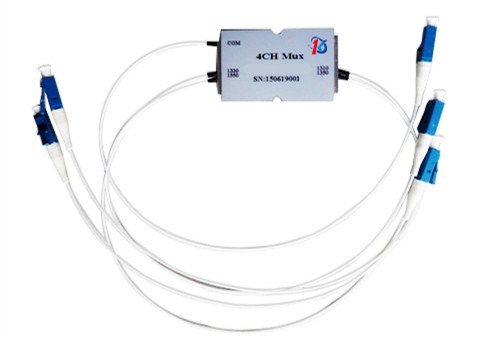
Coarse Wavelength Division Multiplexing (CWDM) mux/demux is an important component in WDM systems, that is typically used to join multiple wavelengths onto a single fiber. Generally, bidirectional or dual-fiber CWDM mux/demux is used to transmit signals bi-directionally. It uses the same wavelengths for transmitting and receiving optical signals on both sides. However, bi-directional CWDM Mux/Demux is not the right choice for all applications. In some cases where there is only one wavelength or fiber available for signal transmission, you have to use single-fiber CWDM Mux/Demux.

In this post, you will learn about single-fiber CWDM Mux/Demux and how it works.

What does a single-fiber CWDM Mux/Demux mean?

Typically, a single-fiber CWDM Mux/Demux has only one simplex line port, which makes it different from a dual-fiber CWDM Mux/Demux design-wise. However, you can find some single-fiber CWDM Mux/Demux with duplex ports. Since it is a single-fiber CWDM Mux/Demux, only one port of the duplex port is used and the other is usually marked N/A.

A single-fiber CWDM Mux/Demux can also achieve dual-way transmission. In bidirectional CWDM networks, each wavelength runs in two opposite directions. On the other hand, each wavelength runs in only one direction in single-fiber CWDM Mux/Demux. But if one wants to create a dual-way transmission link between two different sites, one can use the same one wavelength over duplex fiber with dual-fiber CWDM Mux/Demux or use two wavelengths, i.e. one for the transmitter and the other for the receiver, over simplex fiber with single-fiber CWDM Mux/Demux.

How does a single-fiber CWDM Mux/Demux work?

In a CWDM network, there are 16 wavelengths that you can use to support 8 pairs of dual-way transmission. Let’s assume there are two sites, Site 1 and Site 2. An 8-channel single-fiber CWDM Mux/Demux is installed using 8 wavelengths for signal transmission and the other 8 wavelengths for receiving at Site 1. At Site 2, there is another single-fiber CWDM Mux/Demux installed. However, the wavelengths for transmission and receiving are reversed.

For example, a pair of dual-way optical signals is using 1270 nm wavelength for transmission and 1290 nm for receiving at Site 1, while, at Site 2, 1290nm is used for transmission and 1270 nm is used for receiving. That’s how, with single-fiber CWDM Mux/Demux, one can achieve dual-way transmission.

How do you find the right fiber optic transceivers for single-fiber CWDM Mux/Demux?

Since there are two different wavelengths on a duplex channel port, one can get easily confused while buying fiber optic transceivers for single-fiber CWDM Mux/Demux. The only thing you need to keep in mind is that the selection of fiber optic transceivers for single-fiber CWDM Mux/Demux mainly depends on the wavelength of transceiver/transmission. The fiber optic transceivers used for single-fiber CWDM Mux/Demux are different on the two sites.

All wavelengths in a single-fiber CWDM network go in one direction. For instance, SFP transceivers using 1470nm, 1510nm, 1550nm, and 1590nm are linked with the CWDM Mux/Demux onone side of the network. The SFP transceivers installed on the other side of the network are working on 1490nm, 1530nm, 1570nm, and 1610nm.

Thus, eight wavelengths are used for 4 pair dual-way transmission in a single-fiber CWDM network.