A Fundamental Guide to 2.0μm Single-Mode Fused Couplers

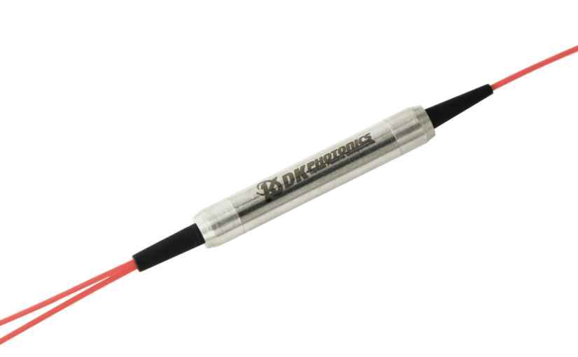
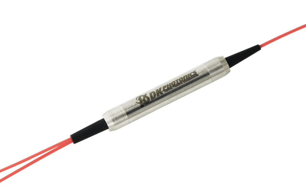
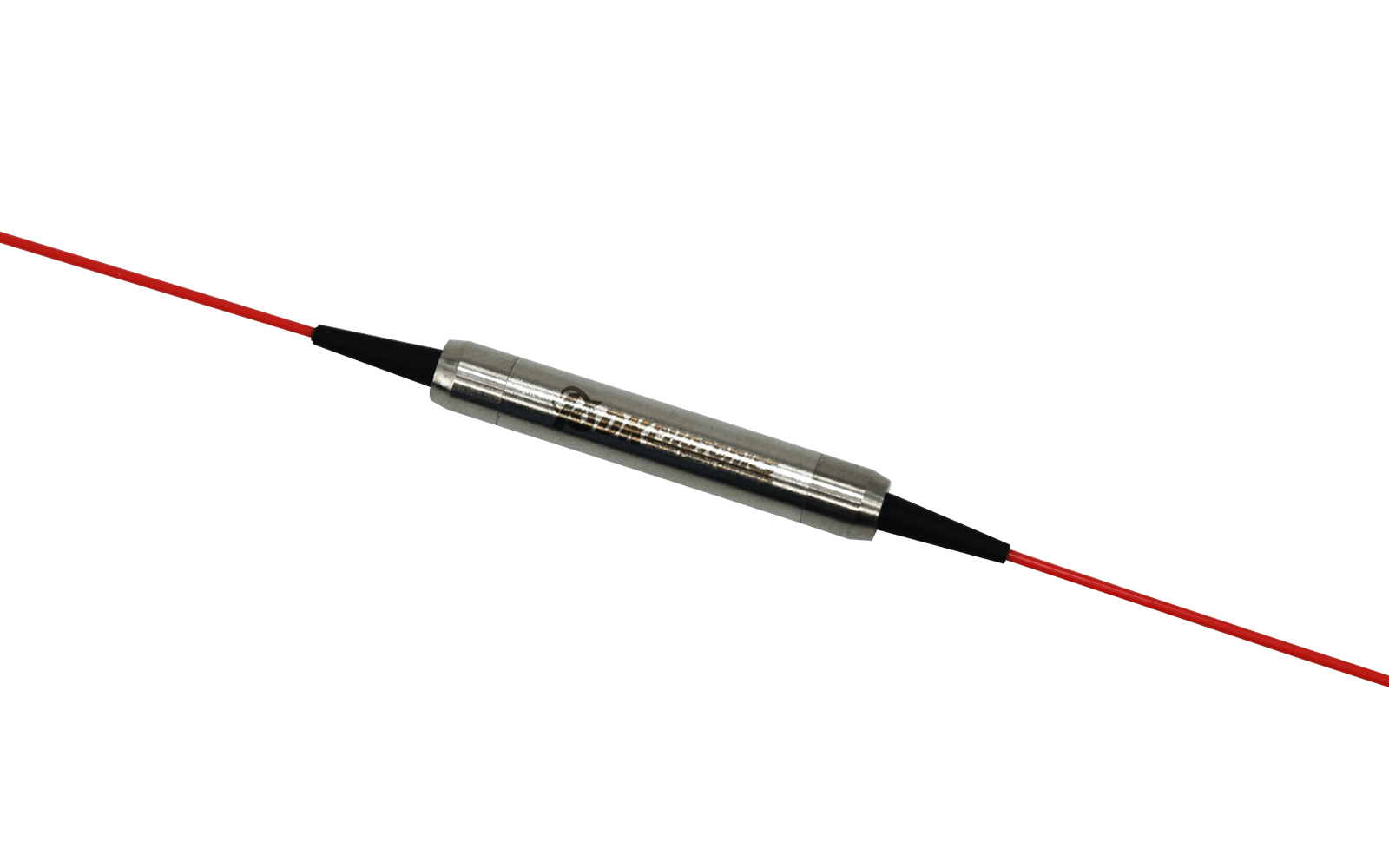
A 2.0μm single-mode fused coupler is an optical passive component designed to split off a portion of light for the purpose of optical monitoring and feedback. In this post, you will learn about the uses of 2.0μm single-mode fused couplers and a lot more.

What are the uses of 2.0μm single-mode fused couplers?

2.0μm single-mode fused couplers are immensely used in fiber amplifier power control and in transmission equipment for performance monitoring and feedback control.

Other important applications of 2.0μm single-mode fused couplers are EDFA, fiber laser, and testing instrumentations.

Apart from splitting optical signals between two fibers, 2.0μm single-mode fused couplers are also used to combine optical signals from two fibers into one fiber.

What is the significance of using fused fibers in an optical coupler?

A 2.0μm single-mode fused coupler is made of 2.0μm single-mode fiber in which only one type of light mode can propagate at a time. The term “fused” represents the construction of this coupler. It means the fiber used in it is designed by stretching, twisting, and fusing the two single-mode fibers so that their cores remain closer to each other.

The method used for fusion provides a simple, rugged, and compact construction to split and combine optical signals.

What is the difference between single-mode fused couplers and multimode fused couplers?

Multimode fused couplers are dependent on modes. In a multimode fused coupler, certain modes within one fiber can pass to the second fiber, while other modes don’t. It means the splitting ratio depends on which modes are excited within the fiber.

On the other hand, single-mode fused couplers transmit only one mode of light. Therefore, they don’t suffer from mode dependency. However, single-mode fused couplers are highly dependent on wavelength.

Even a difference in the wavelength of only 10nm can result in major changes in the splitting ratio in single-mode fused couplers.

Where can I buy 2.0μm single-mode fused couplers?

The 2.0μm Single-Mode Fused Couplers offered by DK Photonics are high-quality and highly reliable because they offer low levels of sensitivity to polarization. It enables them to more effectively monitor and manage optical networks. Besides, its 2.0μm single-mode fused couplers are known for offering low insertion loss, low polarization dependent loss, high stability, and excellent reliability.

At DK Photonics, you can buy 2.0μm Single-Mode Fused Couplers in a broad range of split ratios, lengths, and packaging and can also order these couplers with custom specifications.

Cladding Power Strippers And Their Benefits

The function of a cladding power stripper is to take out any light that travels in the cladding and only measure the light that travels through the core of an optical fiber. This ensures accurate results when measuring how much light is transferred through the core itself, without interference from the surrounding.

Using it can guarantee a wide area for optical power absorption and the safe dissipation of generated heat without harming or damaging the surrounding components.

Benefits of Cladding Power Strippers

Not all power strippers are created equal, and not all customers have the same needs when it comes to stripping or cleaning their cladding panels. In this blog, we’ve put together this list of the top seven benefits of cladding power strippers.

1)   High Stripping Efficiency

Cladding power strippers offer a high stripping efficiency, meaning that they can quickly and easily remove the insulation from wires. This is a huge benefit, as it can save you time and money in the long run. Additionally, cladding power strippers are much more precise than other types of strippers, so you can be sure that you’re not damaging the wire underneath the insulation.

2)   Low Signal Loss and Beam Quality Degradation

If you’ve ever worked with fiber optics, you know that cladding is an important part of the system. Cladding is a thin layer of material that surrounds the core of the fiber and helps to keep the light contained within the core. One of the benefits of cladding is that it helps to reduce signal loss. When light travels through the fiber, some of it is lost due to scattering and absorption. Cladding helps to reduce this loss by keeping the light confined to the core.

3)   High Extinction Ratio 

One of the most important benefits of cladding is its high extinction ratio. This means that when light hits the cladding, very little of it is reflected back into the core.

4)   Stable and Reliable 

When it comes to cladding power strippers, there are many benefits that you may not be aware of. For one, they are much more stable and reliable than other types of strippers on the market. This is due to their unique design and construction. 

5)   Excellent Temperature Stability 

Cladding power strippers have excellent temperature stability, which makes them more resilient and reliable. They are also much more durable than other types of power strippers, making them ideal for use in harsh environments. 

6)   Easy to Use 

Cladding power strippers are much easier to use than other types of power strippers. They can be quickly and easily installed, and they require little maintenance.

7)   High Power Absorption

Did you know that cladding power strippers have the ability to absorb high levels of power? This means that they can be used in a variety of applications where high levels of power are required, such as in industrial settings.

Conclusion

So, with all these benefits, investing in cladding power strippersis a wise choice. If you’re looking for the best cladding power strippers, get in touch with DK photonics. They offer quality and affordable passive optical products. 

A Definitive Guide to Faraday rotation

Introduced by Michael Faraday in 1845, the Faraday rotation or Faraday effects is a magneto-optical phenomenon. The phenomenon means an interaction between light and a magnetic field in a medium. 

Faraday rotation was not a direct development by Michael Faraday. He was searching for experimental evidence that the forces in nature were interconnected. In this process, he made a remarkable discovery by carefully examining the polarization of light when it passed through a transparent material in the presence of a magnetic field. It was observed by him that linearly polarized light propagated through matter parallel to a static magnetic field, causing a rotation of the plane of polarization. Here, the effect was very small. But, with his knowledge and experience, Michael Faraday identified the phenomenon, which is known as Faraday Rotation or Faraday Effect. 

Generally, the Faraday rotation occurs in optically transparent dielectric materials, including liquids, under the influence of magnetic fields. 

What is the physical interpretation of Faraday rotation?

The linear polarization that rotates in the Faraday Effect consists of the superposition of a right and left-circularly polarized beam. The direction of the electric field rotates at the frequency of the light in a clockwise or counter-clockwise direction in the circularly polarized light. 

When you use material, the electric field causes a force on the charged particles known as electrons. The motion effect is circular, circular moving charges creating their own magnetic field along with the external magnetic field. 

This creates two conditions: one, the created field is parallel to the external field for one circular polarization and in the opposing direction for the other polarization direction. Here, the net field is enhanced in one direction and diminished in the opposite direction. This leads to dynamic changes in the interactions for each beam. One of the beams slows down more than the other, causing a phase difference between the left and right-polarized beams. When the two beams are added after the phase shift, it results in a linearly polarized beam with a rotation in the polarization direction. 

The physical properties of the material affect the direction and the intensity of polarization rotation. 

Which devices are based on Faraday rotation?

Faraday isolator- Faraday rotation is needed in Faraday isolators to protect lasers and amplifiers against back-reflected light. For the right use in Faraday isolators, the rotation angle should be close to 45 degrees in the spectral region of interest. It’s said a large attenuation for back-reflected light is obtained by a highly uniform polarization rotation. 

Ring laser resonator– In a ring laser resonator, a Faraday effect or rotation is used to introduce round-trip losses, depending on the direction. This enforces unidirectional operation. A Faraday rotator provides only a very small rotation angle but it’s sufficient because a very small loss difference is considered sufficient.  

Faraday mirror– When a 45-degree rotator combines with an end mirror, it forms a Faraday mirror. A laser beam sent through some amplifier, then reflected at a Faraday mirror and sent back through the amplifier has a polarization directional on returning, which is orthogonal to that of the input beam. This happens even if the polarization state is not preserved within the amplifier. 

Faraday rotation is a big achievement in the science industry. If you want to get devices that are based on Faraday rotation, connect with DK Photonics. 

Important Things to Know About Fiber Lasers

Fiber Bragg Gratings for fiber laser

Fiber lasers are ubiquitous in today’s environment. They are frequently used in industrial settings to carry out cutting, marking, welding, cleaning, texturing, drilling, and much more due to the various wavelengths they can produce. They are also employed in other industries, like telecommunications and medical.

Fiber lasers transmit light along an optical fiber cable consisting of silica glass. Due to its straighter and smaller shape compared to other types of lasers, the resulting laser beam is more precise. Additionally, they feature a compact design, outstanding electrical efficiency, require little maintenance, and have cheap operating expenses.

What Are the Different Types of Fiber Lasers?

In general, the following attributes can be used to classify fiber lasers:

  • Laser Source:

The substance that the laser source is combined with determines the characteristics of a fiber laser. Due to the fact that each of these laser types produces a different wavelength, they are all used for various applications.

  • Mode of Operation:

Different laser designs emit laser beams in various ways. When using “q-switched,” “gain-switched,” or “mode-locked” lasers, high-peak powers can be achieved by pulsing laser beams at a predetermined repetition rate. Alternatively, they might convey the same amount of energy continuously if they were continuous (continuous-wave fiber lasers).

  • Laser Power

The average power of the laser beam is measured in watts or laser power. Compared to low-power lasers, high-power lasers produce more energy more quickly.

  • Mode:

The model describes the size of the optical fiber’s core, which is where light travels. Single-mode fiber lasers and multi-mode fiber lasers are the two different kinds of modes. Single-mode lasers typically transmit laser light more effectively and produce superior beams.

The Benefits of Fiber Lasers

Fiber lasers have advanced significantly and now offer a number of intriguing advantages as a result of the diligent effort of numerous academic and commercial researchers and engineers.

Convenience:

In general, fiber lasers are more compact than conventional lasers of comparable power, and the fact that the laser is housed in a flexible fiber makes beam distribution easier.

  • High power:

Having the gain medium dispersed across a wide area has two implications. First of all, you can get a lot of amplification, and secondly, since there is so much usable surface, dispersing heat is not a problem.

  • Consistent beam quality:

When heat and vibration are present in the environment, fiber lasers still create and deliver high-quality beams.

What Is the Lifespan of a Fiber Laser?

According to many online sources, CO2 lasers only last 30,000 hours while fiber lasers last 100,000 hours. These figures pertain to a quantity known as “mean time between failures” (MTBF), which varies depending on the specific fiber laser in question. For various fiber laser types, you will actually see different numbers.

The MTBF calculates a laser’s dependability by stating the anticipated number of hours of operation before a failure. It is calculated by testing several laser units, adding up the results, and dividing the result by the total number of failures.

This value gives you a good indication of the fiber laser’s dependability even though it cannot precisely tell you how long it can operate.

How Do Fiber Lasers Operate?

Pump light for fiber lasers comes from so-called laser diodes. The light that is sent into the fiber-optic cable is emitted by these diodes. The subsequent step involves creating and amplifying a certain wavelength using optical components. The final step is to shape and release the generated laser beam.

Step 1: The Laser Diodes Produce Light

Step 2: The Fiber-Optic Cable Guides the Pump Light

Step 3: The Laser Cavity Amplifies Light

Step 4: Produce Laser Light with a Specific Wavelength

Step 5: Shape and Release of the Laser Beam

DKphotonic offers a comprehensive range of laser power measurement solutions for various laser types, including fiber lasers.

How to Choose a Suitable Beam Splitter?

Modern laser measurement and positioning systems depend heavily on optical beamsplitters. Although a conventional beamsplitter’s operation is conceptually straightforward, the precision and repeatability of the entire system can be significantly impacted by the performance parameters of the device.

What is a Beamsplitter?

An optical device known as a beamsplitter splits an incident beam of light into two portions. The splitter transmits one part while reflecting the other. If the splitter or reflecting surface is positioned at an angle with respect to the incident light, the reflected light will exit in a desirable direction rather than returning to the source.

Beamsplitters come in two different fundamental categories:

  • NPBSs (non-polarizing beamsplitters):

This kind of splitter divides (splits) a beam into two beams, each of which, independent of polarization, is a portion of the incoming beam. In many optical instrumentation applications, non-polarizing beamsplitters are utilized to disperse portions of a laser beam to other optical sub-assemblies.

  • PBSs, or polarizing beamsplitters:

The S- and P-polarization components of a beam are separated using a splitter of this kind. Optical instrumentation, laser interferometry, and biomedical applications are just a few of the uses for polarizing beamsplitters. Although polarizing beamsplitters frequently come in cube shapes, unique geometries are also available.

Significant Characteristics

In addition to the qualities relating to a beam splitter’s fundamental function, the splitting ratio, other beam splitter parameters might be significant in applications:

  • While some devices are only capable of operating within a specific wavelength range, others are built to operate across the entire visible spectrum. Similar to this, only a limited range of incidence angles may allow beam splitters to function properly.
  • The optical losses differ dramatically between various device kinds. For instance, metallic-coated beam splitters have very substantial losses, whereas dichroic-coated devices may have very low losses, meaning that the total output power is almost equal to the input power.
  • The damage threshold may also be a factor in the losses, and it can be crucial when used with Q-switched lasers.
  • Applications may depend on the spatial layout. Others demand two parallel outputs or some other configuration, while some require that the output ports be positioned at 0° and 90° in relation to the input beam.
  • Sometimes a big open aperture is required for bulk optical devices.

How Should I Choose a Beamsplitter?

  • Application

The application will decide if the objective is to merely divide and/or combine a single beam of light or whether the objective is to filter by wavelength. Choose a plate or cube-type beamsplitter to divide or combine a light beam. A suitable coating on a dichroic filter is required for wavelength separation. Consider the gradient’s steepness when selecting a dichroic beamsplitter because a steeper gradient offers more distinct demarcation between the wavelengths.

  • Source of light

The choice of the beamsplitter is also influenced by the incident light source. A plate beamsplitter will have less chromatic aberration than a cube for white light. Monochromatic light sources give the best performance with cube beamsplitters. A plate beamsplitter would be a better option if the light source is a high-power laser, as the laser light will produce less internal heat.

  • Packaging

Another factor to consider is the packaging. There is sometimes insufficient room to accommodate the offset caused by a plate-type splitter as well as its inclination in various devices, such as interferometers. A cube beamsplitter is recommended in these circumstances.

You must take the form factor, glass homogeneity, coating, transmission range, and damage threshold into account when choosing a beamsplitter. Today, you can find a variety of polarisation beamsplitters online.

What Is a Faraday Mirror and How Does It Work?

Faraday mirrors

A Faraday Mirror is a fiber optic polarization rotator mirror that is used for making a wide range of passive fiber optics components. It is an important invention that made it possible to create passive polarization-maintaining components.

Earlier, the main issue was to maintain the state of polarization as the beam travels across the fiber. This can be easily achieved by using a polarization-maintaining (PM) fiber which is designed for the very same purpose. However, PM fibers and PM-fiber-based devices used to be extremely expensive for many applications and were also difficult to handle.

An optical beam that travels in a typical single-mode (SM) fiber undergoes random changes in birefringence due to stress, vibration, or temperature variation. The use of the Faraday rotator mirror can help resolve this issue.

What is a Faraday mirror?

A Faraday mirror is a fiber optic device that can be used for both the reference mirror and the probing mirror. It works as a phase conjugate mirror by introducing a phase delay of 90 degrees. This feature allows the mirror and the return path of the optical beam to compensate for any induced birefringence automatically.

What is a Faraday mirror made of?

A high-quality Faraday mirror is made of Terbium Gallium Garnet (TGG). TGG is a crystal that is currently the best magneto-optical material for Faraday rotators and isolators. It is considered best because of the high Verdant constant and superior Faraday Effect. It has a higher thermal conductivity and high resistance to laser damage.

How does a Faraday mirror work?

A Faraday mirror works based on the Faraday Effect. In this device, a non-reciprocal rotation of a polarization state occurs as the light beam passes through a special optical medium under the effect of the magnetic field. We will discuss its working with the help of Faraday rotator as its main application is this device.

A Faraday rotator mirror (FRM) consists of a fiber collimator, Faraday rotator, and mirror.

As the orthogonal wave light components pass the optical fiber in the forward direction, they will experience a rotation of 45 degrees in the clockwise direction. When they are reflected by the mirror, they pass the Faraday rotator again, which is a non-reciprocal device, and the polarization state of the reflected optical signal will experience a rotation of another 45 degrees in the same direction as the input signal. Hence, the resultant rotation is 90 degrees. Now, the orthogonal components pass the fiber back but in a complimentary fiber axis and you obtain a linearly polarized light on the close end of the fiber with a rotation of 90 degrees.

Do you need Faraday mirrors to manufacture your fiber optics components or for your research projects? You can easily buy it online at DK Photonics.

Features and Applications of 780nm Optical Isolators

The high-power dual-stage optical isolator 780nm is a polarization-independent fiber element that enables all polarized light to propagate in one direction while blocking it in the opposite direction.

It is not possible to adjust the polarization of input light in many applications. In such instances, a polarization-independent optical fiber isolator with a wavelength of 780nm is required. 780nm optical fiber is a critical component that protects lasers, amplifiers, and ASE sources from instabilities caused by spurious back-reflected light.

Overview of the 780nm Optical Isolators

Low-power lasers benefit from the flexibility, convenience, and performance of the I-780-LM compact designs. I-780-LM covers the wavelength range of 770 to 790nm. A Faraday rotator constructed of LPE film is included in this design.

Due to the absorption of the Faraday rotator material, this type is only advised for low-power applications. For OEM requirements, metal-bonded or hermetic construction alternatives are available. I-780-LM has a standard wavelength of optimization of 780nm.

Applications

  • Semiconductor Laser Modules
  • Tunable Laser Modules
  • Small Form Factor Laser Modules

Features

  • Low Insertion Loss
  • High Isolation
  • Micro-Miniature Size
  • Broad Bandwidth
  • Wide temperature range
  • Polarization alignment

Single Mode / Single Frequency Laser Diode, 780nm DFB, 4mW

The DFB laser is made with discrete-mode (DM) technology, which results in a low-cost laser diode with mode-hop-free tuneability, high SMSR, and a narrow linewidth.

These laser diodes come in a variety of wavelengths ranging from 776 to 784nm, making them ideal for Rb-based atomic clocks, Rubidium sensing, and interferometry applications.

The fiber-coupled butterfly package includes a TEC and a thermistor for precise temperature and wavelength control.

780nm for Rubidium-Based Atomic Clocks

These 780nm lasers operate reliably and without mode hop over a broad wavelength tuning range. These Rubidium-based atomic clocks and spectrometer lasers have a single longitudinal mode. The low linewidth output is ideal for high-performance applications in a variety of environments.

Polarization-Independent Dual-Stage Optical Isolator Fundamentals

The polarization dependence of dual-stage optical isolators using polarizers and a Faraday rotator is a severe problem. The insertion loss will rise as a result of this problem. As a result, optical isolators that are not polarization-dependent are particularly appealing for transmission systems.

By replacing the polarizers with polarizing splitters combiners, it is possible to achieve a polarization-independent design: they divide the input light into two orthogonal states of polarization that run through the Faraday cell separately to experience isolation and are recombined at the output.

Many applications in fiber optic systems necessitate high-power polarization-independent dual-stage optical isolators, which allow inputs with any polarization direction to flow through without PDLs while isolating back reflections (return lights).

The high-power dual-stage optical isolator is a vital component in optical systems. High-power dual-stage optical fiber isolators are used to ensure that laser transmitters and amplifiers are stabilized, and that transmission performance is maintained.

Can an Optical Splitter be Used as a Combiner?

It can be challenging to tell the difference between a Combiner and a Splitter because they have similar appearances. Furthermore, some splitters and combiners might be passive or active, powered or unpowered, adding to the confusion.

Let’s look at the combiner and splitter to see what they’re for.

A Combiner

A combiner is a device that combines multiple input signals of varying frequencies into a single output signal for feeding a single antenna. A combiner basically takes all of the signals and combines them, which is useful when the signals are meant to be combined.

A Splitter

On one end, splitters have a single connection and numerous connections on the other. A splitter receives one signal and splits it into two.

While signal splitting may appear to be the most convenient approach to adding more outlets, keep in mind that each time a signal is split, its power is halved. When you split the transmission, you’re sending half as much signal through each line.

You may think you have a good signal now, but if you divide it too many times, it won’t accomplish the job. Before deciding to split the signal, you need carefully assess whether you have a strong enough signal.

It is frequently recommended that two antennas be used instead of a splitter in places where the signal is extremely weak. The signal will always be divided, whether or not two devices are connected to the splitter.

Polarization Beam Combiner/Splitter

This device can function as a polarization beam combiner, combining light beams from two PM input fibers into a single output fiber, or as a polarization beam splitter, splitting the light from one input fiber into two orthogonal polarization states output fibers.

Polarization Beam Splitter/Combiner

Polarization division multiplexing or demultiplexing in optical systems to boost transmission capacity is an important application of this device. Furthermore, as a pump combiner in optical amplifiers, the device efficiently combines the output from two pump lasers into a single fiber, increasing the optical amplifier’s saturation power and reducing its polarization sensitivity.

The device’s wide operation bandwidth and strong power-handling capacity make it ideal for next-generation amplifier systems. Finally, this compact device has a durable stainless steel package built for strong optical performance and stability, and it has low excess insertion loss, low back reflection, and a high extinction ratio that are comparable to or better than others on the market.

Features:

  • Compact size
  • Low insertion loss
  • High-capacity handling
  • Rugged design

Applications:

  • Mux/DeMux polarisation division
  • Raman amplifiers and EDFA
  • Laser Fiber Systems
  • Fiber Sensor Systems
  • Instruments
  • R&D Laboratories

Polarization Beam Splitter/Combiner is available from DK Photonics, a reputable optical passive component manufacturer based in China. Contact us if you are interested in purchasing Polarization Beam Splitter/Combiner.

How is Polarization Maintained?

Light is a form of electromagnetic wave. It is made of electrical and magnetic fields that oscillate. While you can define light and its effects in terms of the magnetic field, it is easy to characterize its qualities by examining its electrical field.

Polarization Maintained

Light waves can vibrate in different directions. Polarized light is a light that vibrates in just one direction — in a single plane, such as up and down. Unpolarized light is a light that vibrates in more than one direction — in more than one plane, such as up/down and left or right.

How to Obtain Single Polarization?

A polarization filter is the most common way to achieve single polarization. These filters are built of unique materials that can block one of an electromagnetic wave’s two vibrational planes.

A polarization filter is a device that filters out half of the vibrations transmitted through a filter as light passes through it. When unpolarized light passes through a polarization filter, it becomes polarized light, which has half the intensity and vibrates in a single plane.

What is Polarization Maintaining Fiber?

A polarization-maintaining fiber (PM Fiber) is a form of single-mode fiber that maintains polarization. Single-mode fibers can convey polarized light that is randomly polarized. However, PM fiber is designed to transmit one polarization of input light.

The polarization of linearly polarized light waves sent into the fiber is maintained throughout propagation in polarization-maintaining fiber, with little or no cross-coupling of optical power between the polarization modes.

This polarization-maintaining characteristic is critical for some fiber optic components that demand polarized light input, such as external modulators. This property is acquired by creating stresses in the material during the production process. Linear polarization-maintaining fiber (LPMF) and circular polarization maintaining fiber (CPMF) are the two types of polarization-maintaining fiber available.

Applications of Polarization Maintaining Fibers

  1. Fiber optic sensing, interferometry, and slab dielectric waveguides are just a few of the applications for PM optical fibers.
  • PM fibers can be used in coherent and long-distance bidirectional optical transmission systems.
  • They can also be employed in transmission applications where the polarization plane of the optical signal is critical, such as optical sensor transmission lines and optical-electrical integrated circuit coupling.
  • PM fibers are used in lithium niobate modulators, Raman amplifiers, and other polarization-sensitive devices to keep the incoming light polarized and minimize cross-coupling between polarization modes.

What Limits the Performance of PM Fibers?

PM fiber guides light in a linearly polarized form from one location to another in the most typical optical fiber telecommunications applications. It is crucial to meet several requirements to attain this result. In order to avoid launching both slow and fast axis modes, the input light must be highly polarized, resulting in an unpredictable output polarization state.

For the same reason, the electric field of the input light must be precisely aligned with a principal axis (the slow axis by industry convention) of the fiber. The rotational alignment of the joining fibers is crucial if the PM fiber line comprises segments of fiber linked by optical connectors or splices.

Lastly, connectors on PM fibers must be positioned in such a way that internal tensions do not allow the electric field to be projected onto the fiber’s undesired axis.

What is a band-pass filter used for?

Fiber bandpass filters are the optical filters that allow optical signals of certain frequencies to pass through while blocking the optical signals of other frequencies. To block the light of unwanted frequencies, they either absorb the light or reflect it or do both. You can use a band-pass filter to transmit signals in a specific range of frequencies, varying from a narrow band to a wide range.

An Overview of a Band-Pass Filter

Optical bandpass filters are micro-optics devices that transmit (or pass) a specific range (or band) of frequencies and block others. This specific range can include visible light, as well as non-visible wavelengths that fall at the infrared and ultraviolet ends of the spectrum.

Since the filter passes only a certain band of frequencies, the result is an output that comprises only light signals with desired frequencies and wavelengths.

You can define them through various characteristics, including:

  • Blocking level – how effectively and efficiently the bandpass filter is able to eliminate the unwanted wavelengths
  • Peak Transmission – how effectively the incident light is propagated and transmitted
  • Central Wavelength – the wavelength of the light at the center of the transmission band profile
  • Full Width at Half Maximum – the limits of bandwidth between which 50 percent or more light is transmitted

For instance, a very high transmission across the FWHM range with a very low transmission outside of that range is an indication that a bandpass filter is highly effective and has very little noise in the output.

What is a band-pass filter used for?

A fiber bandpass filter is used for blocking unwanted noise signals in a wide range of systems and applications, such as:

  • Fiber amplifiers
  • Fiber lasers systems
  • EDFA systems
  • DWDM systems
  • High-speed communication system
  • Instrumentation applications

Apart from this, optical bandpass filters are also used for anti-reflection and anti-glare coatings, chemical analysis, dielectric mirrors, high reflectors, IR applications, fluorescence filters, long-wave pass, shortwave pass, UV applications, and more.

Generally, bandpass filters are made in two ways. Thin-film filters and coated filters are designed through the deposition of multilayer dielectric coatings onto a substrate. On the other hand, spectral and absorption filters are made by a combination of lamination, cemented layers, and thin film coating.

Fiber bandpass filters are designed based on environmentally stable thin-film filter technology. They work by absorbing or reflecting unwanted wavelengths and transmitting only desirable parts of the light spectrum.

By combing filters and different methods, it is possible to design single laminated bandpass filters with very specific and complex properties to meet the needs of all kinds of electro-optical applications.

DK Photonics is an esteemed optical passive component manufacturer based in China, offering a wide range of fiber optics passive components, including fiber bandpass filters characterized by high isolation, low insertion loss, high extinction ratio, and excellent stability. To buy fiber bandpass filters with standard or customized specifications, please get in touch with us.