Ultrafast laser pulses induce atoms in gold nanodisks to vibrate

In a study that could open doors for new applications of photonics from molecular sensing to wireless communications, Rice University scientists have discovered a new method to tune the light-induced vibrations of nanoparticles through slight alterations to the surface to which the particles are attached.

In a study published online this week in Nature Communications, researchers at Rice’s Laboratory for Nanophotonics (LANP) used ultrafast laser pulses to induce the atoms in gold nanodisks to vibrate. These vibrational patterns, known as acoustic phonons, have a characteristic frequency that relates directly to the size of the nanoparticle. The researchers found they could fine-tune the acoustic response of the particle by varying the thickness of the material to which the nanodisks were attached.

“Our results point toward a straightforward method for tuning the acoustic phonon frequency of a nanostructure in the gigahertz range by controlling the thickness of its adhesion layer,” said lead researcher Stephan Link, associate professor of chemistry and in electrical and computer engineering.

Rice University researchers (clockwise from front) Man-Nung Su, Wei-Shun Chang and Fangfang Wen discovered a new method to tune the light-induced vibrations of nanoparticles through slight alterations to the surface to which they are attached.

Light has no mass, but each photon that strikes an object imparts a miniscule amount of mechanical motion, thanks to a phenomenon known as radiation pressure. A branch of physics known as optomechanics has developed over the past decade to study and exploit radiation pressure for applications like gravity wave detection and low-temperature generation.

Link and colleagues at LANP specialize in another branch of science called plasmonics that is devoted to the study of light-activated nanostructures. Plasmons are waves of electrons that flow like a fluid across a metallic surface.

When a light pulse of a specific wavelength strikes a metal particle like the puck-shaped gold nanodisks in the LANP experiments, the light energy is converted into plasmons. These plasmons slosh across the surface of the particle with a characteristic frequency, in much the same way that each phonon has a characteristic vibrational frequency.

The study’s first author, Wei-Shun Chang, a postdoctoral researcher in Link’s lab, and graduate students Fangfang Wen and Man-Nung Su conducted a series of experiments that revealed a direct connection between the resonant frequencies of the plasmons and phonons in nanodisks that had been exposed to laser pulses.

“Heating nanostructures with a short light pulse launches acoustic phonons that depend sensitively on the structure’s dimensions,” Link said. “Thanks to advanced lithographic techniques, experimentalists can engineer plasmonic nanostructures with great precision. Based on our results, it appears that plasmonic nanostructures may present an interesting alternative to conventional optomechanical oscillators and high power isolator

Chang said plasmonics experts often rely on substrates when using electron-beam lithography to pattern plasmonic structures. For example, gold nanodisks like those used in the experiments will not stick to glass slides. But if a thin substrate of titanium or chromium is added to the glass, the disks will adhere and stay where they are placed.

“The substrate layer affects the mechanical properties of the nanostructure, but many questions remain as to how it does this,” Chang said. “Our experiments explored how the thickness of the substrate impacted properties like adhesion and phononic frequency.”

Link said the research was a collaborative effort involving research groups at Rice and the University of Melbourne in Victoria, Australia.

“Wei-Shun and Man-Nung from my lab did the ultrafast spectroscopy,” Link said. “Fangfang, who is in Naomi Halas’ group here at Rice, made the nanodisks. John Sader at the University of Melbourne, and his postdoc Debadi Chakraborty calculated the acoustic modes, and Yue Zhang, a Rice graduate student from Peter Nordlander’s group at Rice simulated the optical/plasmonic properties. Bo Shuang of the Landes’ research group at Rice contributed to the analysis of the experimental data.”

The research was supported by the Robert A. Welch Foundation and the Department of Defense’s Multi-University Research Initiative. Additional co-authors include Zhang, Shuang, Nordlander and Halas, all of Rice; and Chakraborty and Sader, both of the University of Melbourne in Victoria, Australia.

About DK Photonics

DK Photonics – www.dkphotonics.com  specializes in designing and manufacturing of high quality optical passive components mainly for fiber laser applications such as 1064nm high power isolator, Cladding Power Stripper, Multimode High Power Isolator, pump combiner,1064nm Band-pass Filter,(6+1)X1 Pump and Signal Combiner, PM Circulator, PM Isolator, optical Coupler. More information, please contact us.

Polarization Dependent Isolator vs Polarization Independent Isolator

Connectors and other types of optical devices on the output of the transmitter may cause reflection, absorption, or scattering of the optical signal. These effects on the light beam may cause light energy to be reflected back at the source and interfere with source operation. In order to reduce the effects of the interference, an optical isolator is usually used. Optical isolator allows a beam of light to stream through a single one way direction. At the same time, it prevents the light from going back in the opposite direction. According to the polarization characteristics, optical isolators can be divided into two types, including polarization dependent isolator and polarization independent isolator. The polarizer-based module makes a polarization dependent isolator, and the birefringent crystal-based structure makes a polarization independent isolator. You may be very confused about them as you find that there is only a little difference via their names. So, what are they and what are the differences between them? This paper will give you the answer.

Polarization Dependent Isolator

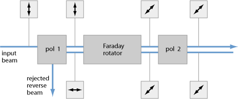
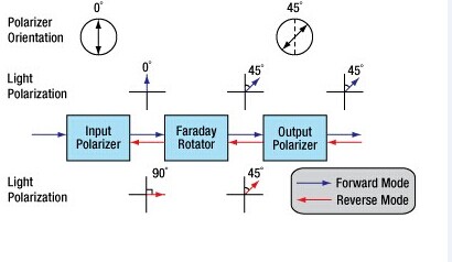
The polarization dependent isolator consists of three parts, an input polarizer , a Faraday rotator, and an output polarizer. Light traveling in the forward direction becomes polarized vertically by the input polarizer. The Faraday rotator will rotate the polarization by 45°. The analyser then enables the light to be transmitted through the isolator.

Polarization-Dependent-Isolator

Light traveling in the backward direction becomes polarized at 45° by the analyser. The Faraday rotator will again rotate the polarization by 45°. This means the light is polarized horizontally. Since the polarizer is vertically aligned, the light will be extinguished.

The picture shows us a Faraday rotator with an input polarizer, and an output analyser. For a polarization dependent isolator, the angle between the polarizer and the analyser, is set to 45°. The Faraday rotator is chosen to give a 45° rotation.

Because the polarization of the source is typically maintained by the system, polarization dependent isolator is widely used in free space optical systems.

Polarization Independent Isolator

The polarization independent isolator also consists of three parts, an input birefringent wedge, a Faraday rotator, and an output birefringent wedge. Light traveling in the forward direction is split by the input birefringent wedge into its vertical (0°) and horizontal (90°) components, called the ordinary ray (o-ray) and the extraordinary ray (e-ray) respectively. The Faraday rotator rotates both the o-ray and e-ray by 45°. This means the o-ray is now at 45°, and the e-ray is at −45°. The output birefringent wedge then recombines the two components.

Polarization-Independent-Isolator

Light traveling in the backward direction is separated into the o-ray at 45, and the e-ray at −45° by the birefringent wedge. The Faraday Rotator again rotates both the rays by 45°. Now the o-ray is at 90°, and the e-ray is at 0°. Instead of being focused by the second birefringent wedge, the rays diverge. The picture shows the propagation of light through a polarization independent isolator.

While polarization dependent isolator allows only the light polarized in a specific direction, polarization independent isolator transmit all polarized light. So it is usually widely used in optical fiber amplifier.

Comparison of Polarization Dependent Isolator and Polarization Independent Isolator

In fact, you have already understood these two types of isolators according to the contents above. We can see their similarities and differences through the comparison of their definition, working principle and applications. Both of them consist of three parts and have a same principle based on Faraday effect. However, to overcome the limitation of polarization dependent isolator, polarization independent isolator has been developed. Regardless of the polarization state of the input beam, the beam will propagate through the isolator to the output fiber and the reflected beam will be isolated from the optical source. If the extinction ratio is important, a polarization dependent isolator should be used with either polarization maintaining fibers or even regular single-mode fibers. If the system has no polarization dependence, a polarization independent isolator will be the obvious choice.

About DK Photonics

DK Photonics – www.dkphotonics.com  specializes in designing and manufacturing of high quality optical passive components mainly for fiber laser applications such as 1064nm high power isolator, Cladding Power Stripper, Multimode High Power Isolator, pump combiner,1064nm Band-pass Filter,(6+1)X1 Pump and Signal Combiner, PM Circulator, PM Isolator, optical Coupler. More information, please contact us.
2~18CH CWDM MUX/DEMUX Module from DK Photonics

The key components in a WDM system are the optical wavelength multiplexer (MUX), and the de-multiplexer (DEMUX). In general, a CWDM (coarse WDM) MUX/DEMUX deals with small numbers of wavelengths, typically eight, but with large spans between wavelengths (spaced typically at around 20nm). A DWDM (dense WDM) MUX/DEMUX deals with narrower wavelength spans (as small as 0.8nm, 0.4nm or even 0.2nm), and can accommodate 40, 80, or even 160 wavelengths.

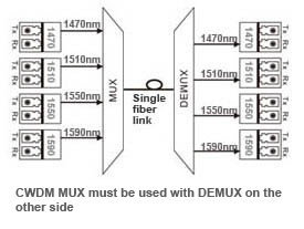
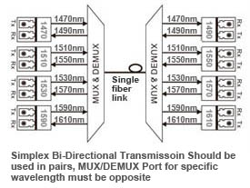
The one kind of DK Photonics LGX CWDM MUX/DEMUX modules are bi-directional passive optical multiplexers and de-multiplexers, allowing multiple optical signals at different wavelengths to pass through a single optical fiber strand.

simplex-bidi-transmission-cwdm-mux-demux

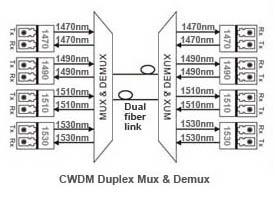
The second DK Photonics ABS CWDM MUX/DEMUX modules are duplex fiber link bi-directional multiplexers and de-multiplexers, allowing multiple optical signals’ at different wavelengths to pass through duplex optical fiber.

duplex-bidi-transmission-cwdm-mux-demux

The last one kind is simplex directional CWDM MUX only or CWDM DEMUX only. The kind of mux and demux must be used with each other.

simplex-directional-transmission-cwdm-mux-demux

CWDM MUX/DEMUX solution lets operators make full use of available fiber bandwidth in local loop and enterprise architectures. Our CWDM MUX/DEMUX modules split up to 18 channels (20 nm spaced) to a single fiber. The standard packages are ABS Plastic Box, 19″ Rack Mount Chassis CWDM Mux/Demux  and LGX Metal Box Mux/Demux. No matter what kinds of connectors (such as FC, ST, SC, LC, etc.) are all available and we can also mix connectors on one device.

CWDM MUX+DEMUX 8 Channels (Dual Fiber) Module

DK Photonics offers a wide range of WDM (Wavelength Division Multiplexing) optical networking products that allow transport of any mix of services from 2Mbps up to 100Gbe over dark fiber and WDM networks providing for the entire set of the most demanding CWDM and DWDM network infrastructure needs.

2015-Fiber Optic Communication Collimators Market Forecast

Fiber optic collimator lens arrays are forecast with strong value-based growth rates of more than 30% per year (2014-2019)…

Aptos, CA (USA) – March 23, 2015 — ElectroniCast Consultants, a leading market research & technology forecast consultancy addressing the fiber optics communications industry, today announced the release of a new market forecast of the global market consumption and technology trends of small beam collimating lens assemblies in fiber optic communication (including telecommunication, datacom and cable TV) passive and active/integrated (hybrid) components/devices.

The market study covers single lens assemblies, 2-12 lens arrays, and arrays with more than 12 lenses. Both of the lens array categories are forecast with strong growth rates of more than 30% per year (2014-2019). Single lens fiber optic collimator assemblies held the global market share lead, with over 80% in 2014.

“Collimator lenses are used in a variety of photonic products; however this market study forecasts the use of micro-sized collimator lens assemblies, which are used specifically in optical communication components/devices(such as 8CH LGX CWDM Module). Fiber optic collimator lens assemblies serve as a key indicator of the growth of the fiber optic communication component industry,” said Stephen Montgomery, Director of the Fiber Optic Component group at the California-based consultancy.

ElectroniCast defines lens assemblies as “loose” lenses (one or more), which are attached to an optical fiber or fitted/attached into (or on) a planar waveguide/array substrates or other device(s), such as a ferrule, for the purpose of collimating light for optical fiber communication.

The global consumption of fiber optic collimator lens assemblies, which are used in commercial optical communication applications, reached $287.2 million in 2014, an increase of 8.7% over the previous year.

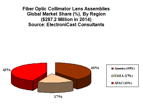
Consumption is based on the geographical (region) location where the lens assembly is first used into (the) higher-level component or module package; therefore, ElectroniCast forecasts that the Asia Pacific Region will hold the market share lead for most of the timeframe covered in the forecast period.  America, led by the United States, is forecast to remain in the 2nd-place market position until 2019.  Europe is forecast to maintain moderate-to-strong growth, as the region is steadily involved in value-added building (and use) of sub-assemblies and equipment.  Market forecast data in the ElectroniCast report refers to consumption (use) for a particular calendar year; therefore, this data is not cumulative data.

DK Photonicswww.dkphotonics.com  specializes in designing and manufacturing of high quality optical passive components mainly for telecommunication, fiber sensor and fiber laser applications,such as 1064nm High Power Isolator,1064nm Components, PM Components, (2+1)x1 Pump Combiner,Pump Laser Protector,Mini-size CWDM,100GHz DWDM,Optical Circulator,PM Circulator,PM Isolator,Fused Coupler,Mini Size Fused WDM.

The Asia Pacific region is the leader in value of the fiber optic communication collimators market; however, the American region is forecast to take the lead in 2019 …

fiber optic collimator

2015-Fiber Optic Sensors Global Market Forecast

According to ElectroniCast, the combined use of Continuous Distributed and Point fiber optics sensors reached $2.28 Billion in 2014…

Aptos, CA (USA) – February 18, 2015  — ElectroniCast Consultants, a leading market/technology forecast consultancy, today announced the release of their market forecast and analysis of the global consumption selected Fiber Optic Point Sensors and Continuous Distributed Fiber Optics Sensor systems.

According to ElectroniCast, the consumption value of the combined use of Continuous Distributed and Point fiber optics sensors reached $2.28 Billion in 2014.

Continuous Distributed fiber optic sensor systems involve the optic fiber with the sensors embedded with the fiber.  ElectroniCast counts each Point fiber optic sensor as one unit; however, the volume of Distributed Continuous fiber optic sensors is based on a complete optical fiber line and associated other components, which are defined as a system.

“Since a distributed continuous optical fiber line (system) may have 100s of sensing elements in a continuous-line, it is important to note that ElectroniCast counts all of those sensing elements in a distributed continuous system as one (system) unit – only.  In the case of some applications, the price of the system may be several thousand dollars,” stated Stephen Montgomery, Director of the Fiber Optics Components group at ElectroniCast Consultants.

“POINT sensors are often used in Distributed fiber optic sensor systems (installed at multiple-points/ point-to-point); however, we count their use in the Point fiber optic sensor category and not in the continuous (non-stop) distributed sensor category,” Montgomery added.

DK Photonicswww.dkphotonics.com  specializes in designing and manufacturing of high quality optical passive components mainly for telecommunication, fiber sensor and fiber laser applications,such as 1064nm High Power Isolator,1064nm Components, PM Components, (2+1)x1 Pump Combiner,Pump Laser Protector,Mini-size CWDM,100GHz DWDM,Optical Circulator,PM Circulator,PM Isolator,Fused Coupler,Mini Size Fused WDM.

DATA FIGURE

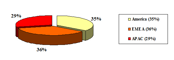
According to ElectroniCast, The EMEA region held a slight lead in the worldwide consumption value of fiber optic sensors last year (2014)…

Fiber Optic Sensor Global Consumption Regional Market Forecast

($2.28 Billion in 2014)

Source: ElectroniCast Consultants

fiber optic coupler

2015-Optical Isolators Global Market Trends

According to ElectroniCast, the worldwide optical isolator consumption reached $584.2 million last year…. 

Aptos, California (USA) – March 2, 2015 — ElectroniCast Consultants, a leading market research & technology forecast consultancy addressing the fiber optics communications industry, today announced the release of a new market forecast of the global consumption of optical isolators in optical communication and specialty applications.

According to ElectroniCast, the worldwide optical isolator consumption reached $584.2 million last year in 2014.  Optical isolator use was led by Telecommunication applications with a 72 percent market share or $419.2 million.  Market data in this study report refers to consumption (use) for a particular calendar year; therefore, this data is not cumulative data.

1064nm-High-Power-Collimated-Free-space-Beam-Output-Isolator

Optical isolators are devices that allow light to be transmitted in only one direction. They are most often used to prevent any light from reflecting back down the optical fiber, as this light would enter the source and cause backscattering and feedback problems. This is especially important for high data rate transceivers and transponders, or those devices requiring long span lengths between transceiver pairs. Optical feedback degrades signal-to-noise ratio and consequently bit-error rate.

1550nm Polarization Isensitive Isolator-300mW

“Continuing demand for upgrading communication networks to accommodate rapidly increasing bandwidth requirements will drive the steady consumption of optical fiber links. Optical isolators are used in with high-speed transmitters that are required to transmit longer distances and/or multiple wavelength transmitters,” stated Stephen Montgomery, Director of the Fiber Optics Components group at ElectroniCast Consultants.

Optical isolators are not widely used in Private Enterprise applications. The worldwide use of fiber optic isolators in Cable TV device deployments are forecast to grow in value at an annual rate of 4.9 percent (2014-2019), as optical fiber is deployed closer to the home driven by multi-media applications.

Optical isolator units are used in a variety of Military/Aerospace applications requiring rigorous testing and harsh environment fiber optic (HEFO) certification to ensure reliability and performance.  Laser-based fiber optic technology incorporating optical isolators are used in a wide variety of air, sea, ground, and space applications.

A major user-group within the Specialty application category is instrument-Laboratory/ R&D.  Optical isolators are used for noise reduction, medical imaging, pulse selection for mode locked lasers, sensing, regeneration switches, disc master, optical trapping, phase shifters, frequency modulation spectroscopy and general shuttering. The optical isolators are also used in sensing for industrial, structures and other many other communication product-oriented manufacturing/test/R&D uses.


DK Photonicswww.dkphotonics.com  specializes in designing and manufacturing of high quality optical passive components mainly for telecommunication, fiber sensor and fiber laser applications,such as 1064nm High Power Isolator,1064nm Components, PM Components, (2+1)x1 Pump Combiner,Pump Laser Protector,Mini-size CWDM,100GHz DWDM,Optical Circulator,PM Circulator,PM Isolator,Fused Coupler,Mini Size Fused WDM.

2015-Fiber Optic Circulators Global Market Analysis

The market value of fiber optic circulators increased 10.77% in 2014…

Aptos, CA (USA) – March 9, 2015 ElectroniCast Consultants, a leading market research & technology forecast consultancy addressing the fiber optics communications industry, today announced the release of a new market forecast of the global consumption of fiber optic circulators in optical communications.

During 2014-2019, the consumption value is forecast to increase with rising quantity growth partially offset by declining average prices.

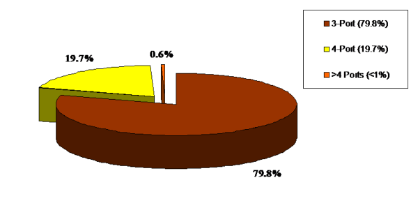
The fiber optic circulator market is presented by the following port-count configurations: 3-Ports; 4-Ports; and more than 4-Ports (> 4 – Ports).  According to ElectroniCast, the worldwide use of fiber optic circulators reached $244.8 million in 2014, an increase of 10.77% over he total consumption value of $227.4 million in 2013.  3-Port fiber optic circulators held an 80% market share in 2014.  Well-over 70% of the 3-Port fiber optic circulator market value in 2014 was in Telecommunication applications.

Telecommunications is set to maintain its dominant market share lead throughout the forecast period.  Specialty applications (R&D laboratory, sensors, test equipment, oil/gas, other) are set to maintain the position of second-place, according to the ElectroniCast market forecast and analysis study.

Fiber Optic Circulators are non-reciprocal devices, which means that changes in the properties of light passing through the device are not reversed when the light passes through in the opposite direction. The optical device is commonly used in a wide variety of systems, here are just a few examples: dispersion compensation, optical sensors, optical amplifiers, WDM systems, optical add/drops multiplexing (OADMs) and test/measurement instruments such as optical time-domain reflectometers (OTDRs), remote fiber (optic) test systems (RFTS) and other test equipment.

The deployment of optical fiber in the metro/access, the continuing demand for upgrading networks to accommodate rapidly increasing bandwidth requirements, plus the need for additional monitoring and testing of the optical fiber networks will drive the steady consumption of fiber optic circulators.

According to ElectroniCast Consultants, 3-Port fiber optic circulators held an 80% (value) market share in 2014…

Fiber Optic Circulator Global Market Share (%), By Port Count

(2014 – ElectroniCast Estimate: $244.8 Million)


fiber optic circulators


DK Photonicswww.dkphotonics.com  specializes in designing and manufacturing of high quality optical passive components mainly for telecommunication, fiber sensor and fiber laser applications,such as 1064nm High Power Isolator,1064nm Components, PM Components, (2+1)x1 Pump Combiner,Pump Laser Protector,Mini-size CWDM,100GHz DWDM,Optical Circulator,PM Circulator,PM Isolator,Fused Coupler,Mini Size Fused WDM.

Introduction of the Transients in Optical WDM Networks

A systems analysis continues to be completed to consider dynamical transient effects in the physical layer of an Optical WDM Network. The physical layer dynamics include effects on different time scales. Dynamics from the transmission signal impulses possess a scale of picoseconds. The timing recovery loops in the receivers be employed in the nanoseconds time scale. Optical packet switching in the future networks will have microsecond time scale. Growth and development of such optical networks is yet continuing. Most of the advanced development work in optical WDM networks is presently focused on circuit switching networks, where lightpath change events (for example wavelength add/drop or cross-connect configuration changes) happen on the time scale of seconds.

It is focused on the dynamics from the average transmission power associated with the gain dynamics in Optical Line Amplifiers (OLA). These dynamics may be triggered by the circuit switching events and have millisecond time scale primarily defined by the Amplified Spontaneous Emission (ASE) kinetics in Erbium-Doped Fiber Amplifiers (EDFAs). The transmission power dynamics will also be influenced by other active components of optical network, for example automatically tunable 100GHz DWDM, spectral power equalizers, or other light processing components. When it comes to these dynamics, a typical power of the lightpath transmission signal is recognized as. High bandwidth modulation from the signal, which actually consists of separate information carrying pulses, is mostly ignored.

14_nodes Ring WDMRing WDM networks implementing communication between two fixed points are very well established technology, in particular, for carrying SONET over the WDM. Such simple networks with fixed WDM lighpaths happen to be analyzed in many detail. Fairly detailed first principle models for transmission power dynamics exist for such networks. These models are implemented in industrial software allowing engineering design calculations and dynamical simulation of these networks. Such models could possibly have very high fidelity, but their setup, tuning (model parameter identification) and exhaustive simulations covering a variety of transmission regimes are potentially very labor intensive. Adding description of new network components to such model could need a major effort.

14_nodes Mesh WDMThe problems with detailed first principle models is going to be greatly exacerbated for future Mesh WDM networks. The near future core optical networks will be transparent to wavelength signals on a physical layer. In such network, each wavelength signal travels through the optical core between electronic IP routers around the optical network edge using the information contents unchanged. The signal power is attenuated in the passive network elements and boosted by the optical amplifiers. The lightpaths is going to be dynamically provisioned by Optical Cross-Connects (OXCs), routers, or switches independently on the underlying protocol for data transmission. Such network is basically a circuit switched network. It might experience complex transient processes of the average transmission power for every wavelength signal at the event of the lightpath add, drop, or re-routing. A mix of the signal propagation delay and channel cross-coupling might result in the transmission power disturbances propagating across the network in closed loops and causing stamina oscillations. Such oscillations were observed experimentally. Additionally, the transmission power and amplifier gain transients could be excited by changes in the average signal power because of the network traffic burstliness. If for some period of time the wavelength channel bandwidth is not fully utilized, this could result in a loss of the average power (average temporal density of the transmitted information pulses).

First circuit switched optical networks are already being designed and deployed. Fraxel treatments develops rapidly for metro area and long term networks. Engineering design of circuit switched networks is complicated because performance has to be guaranteed for all possible combinations of the lightpaths. Further, as such networks develop and grow, they potentially need to combine heterogenous equipment from a variety of vendors. A system integrator (e.g., DK Photonics) of such network might be different from subsystems or component manufacturer. This creates a necessity of developing adequate means of transmission power dynamics calculations which are suitable for the circuit switched network business. Ideally, these methods should be modular, independent on the network complexity, and use specifications on the component/subsystem level.

DK Photonics has technical approach to systems analysis that’s to linearize the nonlinear system around a fixed regime, describe the nonlinearity like a model uncertainty, and apply robust analysis that guarantees stability and gratifaction conditions within the presence of the uncertainty. For a user of the approach, there is no need to understand the derivation and system analysis technicalities. The obtained results are very simple and relate performance to basic specifications of the network components. These specifications are somewhat not the same as those widely used in the industry, but could be defined from simple experimentation using the components and subsystems. The obtained specification requirements may be used in growth and development of optical amplifiers, equalizers, optical attenuators, other transmission signal conditioning devices, OADM Modules, OXCs, and any other optical network devices and subsystems influencing the transmission power.

DK Photonics – www.dkphotonics.com  specializes in designing and manufacturing of high quality optical passive components mainly for telecommunication, fiber sensor and fiber laser applications,such as WDM, FWDM, CWDM, DWDM, OADM,Optical Circulator, Isolator, PM Circulator, PM Isolator, Fused Coupler, Fused WDM, Collimator, Optical Switch and Polarization Maintaining Components, Pump Combiner, High power isolator, Patch Cord and all kinds of connectors.

Large Mode Area Fibers

Optical fibers with relatively large mode areas and a single transverse mode or only a few modes.

For some applications, it is desirable to use optical fibers with a large mode area (LMA fibers) – often with single-mode guidance. Due to the reduced optical intensities, such fibers effectively have lower nonlinearities and a higher damage threshold, which makes them suitable for example for the Amplification of intense Pulses or single-frequency signals in Fiber amplifiers, or in case of passive fibers for delivery of such light. While standard single-mode fibers have an Effective Mode Area below 100 μm2, large mode area fibers reach values of hundreds or even thousands of μm2.

DK Photonics – www.dkphotonics.com  specializes in designing and manufacturing of high quality optical passive components mainly for fiber laser applications such as 1064nm high power isolator, Cladding Power Stripper, Multimode High Power Isolator, pump combiner,1064nm Band-pass Filter,(6+1)X1 Pump and Signal Combiner, PM Circulator, PM Isolator, optical Coupler. More information, please contact us.
Testing Fiber Optic Splitters Or Other Passive Devices

A fiber optic splitter is a device that splits the fiber optic light into several parts by a certain ratio. For example, when a beam of fiber optic light transmitted from a 1X4 equal ratio splitter, it will be divided into 4-fiber optic light by equal ratio that is each beam is 1/4 or 25% of the original source one. A Optical Splitter is different from WDM. WDM can divide the different wavelength fiber optic light into different channels. fiber optic splitter divide the light power and send it to different channels.

Most Splitters available in 900µm loose tube and 250µm bare fiber. 1×2 and 2×2 couplers come standard with a protective metal sleeve to cover the split. Higher output counts are built with a box to protect the splitting components.

Testing a coupler or splitter (both names are used for the same device) or other passive fiber optic devices like switches is little different from testing a patchcord or cable plant using the two industry standard tests, OFSTP-14 for double-ended loss (connectors on both ends) or FOTP-171 for single-ended testing.

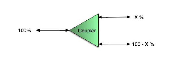
First we should define what these passive devices are. An optical coupler is a passive device that can split or combine signals in optical fibers. They are named by the number of inputs and outputs, so a splitter with one input and 2 outputs is a 1×2 fiber splitter, and a PON splitter with one input and 32 outputs is 1×32 splitter. Some PON splitters have two inputs so it would be a 2X32. Here is a table of typical losses for splitters.

Splitter-Ratio

Important Note! Mode Conditioning can be very important to testing couplers. Some of the ways they are manufactured make them very sensitive to mode conditioning, especially multimode but even singlemode couplers. Singlemode couplers should always be tested with a small loop in the launch cable (tied down so it does not change and set the 0dB reference with the loop.) Multimode couplers should be mode conditioned by a mandrel wrap or similar to ensure consistency.

Let’s start with the simplest type. Shown below is a simple 1X2 splitter with one input and two outputs. Basically, in one direction it splits the signal into 2 parts to couple to two fibers. If the split is equal, each fiber will carry a signal that is 3dB less than the input (3dB being a factor of two) plus some excess loss in the coupler and perhaps the connectors on the splitter module. Going the other direction, signals in either fiber will be combined into the one fiber on the other side. The loss is this direction is a function of how the coupler is made. Some couplers are made by twisting two fibers together and fusing them in high heat, so the coupler is really a 2X2 coupler in which case the loss is the same (3dB plus excess loss) in either direction. Some splitters use optical integrated components, so they can be true splitters and the loss in each direction may different.

optical coupler

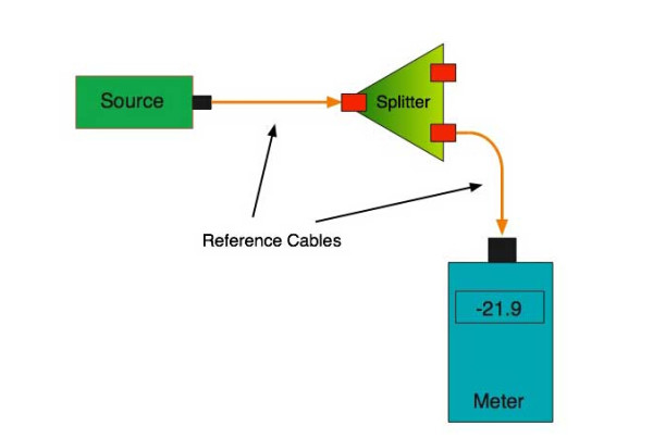
So for this simple 1X2 splitter, how do we test it? Simply follow the same directions for a double-ended loss test. Attach a launch reference cable to the test source of the proper wavelength (some splitters are wavelength dependent), calibrate the output of the launch cable with the meter to set the 0dB reference, attach to the source launch to the splitter, attach a receive launch cable to the output and the meter and measure loss. What you are measuring is the loss of the splitter due to the split ratio, excess loss from the manufacturing process used to make the splitter and the input and output connectors. So the loss you measure is the loss you can expect when you plug the splitter into a cable plant.

To test the loss to the second port, simply move the receive cable to the other port and read the loss from the meter. This same method works with typical PON splitters that are 1 input and 32 outputs. Set the source up on the input and use the meter and reference cable to test each output port in turn.

What about the other direction from all the output ports? (In PON terms, we call that upstream and the other way from the 1 to 32 ports direction downstream.) Simply reverse the direction of the test. If you are tesing a 1X2 splitter, there is just one other port to test, but with a 1X32, you have to move the source 32 times and record the results on the meter.

fiber-splitter

What about multiple input and outputs, for example a 2X2 coupler? You would need to test from one input port to the two outputs, then from the other input port to each of the two outputs. This involves a lot of data sometimes but it needs to be tested.

There are other tests that can be performed, including wavelength variations (test at several wavelengths), variations among outputs (compare outputs) and even crosstalk (put a signal on one output and look for signal on other outputs.)

Once installed, the splitter simply becomes one source of loss in the cable plant and is tested as part of that cable plant loss for insertion loss testing. Testing splitters with an OTDR is not the same in each direction.

Other Passive Devices

There are other passive devices that require testing, but the test methods are similar.

Fiber optic switches are devices that can switch an input to one of several outputs under electronic control. Test as you would the splitter as shown above. Switches may be designed for use in only one direction, so check the device specifications to ensure you test in the proper direction. Switches may also need testing for consistency after multiple switch cycles and crosstalk.

Attenuators are used to reduce signal levels at the receiver to prevent overloading the receiver. There is a page on using attenuators that you should read. If you need to test an attenuator alone, not part of a system, use the test for splitters above by using the attenuator to connect the launch and receive cables to see if the loss is as expected.

Wavelength-division multiplexers can be tricky to test because they require sources at a precise wavelenth and spectral width, but otherwise the test procedures are similar to other passive components.

Fiber optic couplers or splitters are available in a wide range of styles and sizes to split or combine light with minimal loss. All couplers are manufactured using a very simple proprietary process that produces reliable, low-cost devices. They are physically rugged and insensitive to operating temperatures. Couplers can be fabricated in custom fiber lengths and/or with terminations of any type.

DK Photonicswww.dkphotonics.com  specializes in designing and manufacturing of high quality optical passive components mainly for telecommunication, fiber sensor and fiber laser applications,such as PLC Splitter, WDM, FWDM, CWDM, DWDM, OADM,Optical Circulator, Isolator, PM Circulator, PM Isolator, Fused Coupler, Fused WDM, Collimator and Polarization Maintaining Components, Pump Combiner, High power isolator, Patch Cord and all kinds of connectors.