Pump and signal combiner for bi-directional pumping of all-fiber lasers and amplifiers(2)

2. Optical design and relevant ray paths of the fiber combiner

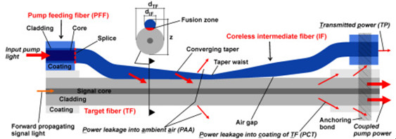
A schematic side view of the side-pump combiner consisting of a pump feeding fiber (PFF), a coreless intermediate fiber (IF) and a target fiber (TF) is shown in Fig. 1

high-power-isolator-1064nm

Fig. 1 Schematic side view of a side-pumped double-clad fiber including important ray paths.

. The diameter of the PFF core and the cladding was 105 and 125 µm, respectively. The NA of the pure silica PFF core used in the simulations was 0.15, 0.22 or 0.3 and, therefore, the refractive index of the PFF cladding was depressed in comparison to the refractive index of the PFF core. The cladding of the PFF was surrounded by a polymer coating only for mechanical protection of the fiber. Therefore, the PFF preserved the same waveguide properties after removal of the polymer coating. In the case of side-pumping without an IF, the higher refractive index of the core of the PFF would suppress the pump power transfer into the TF as long as the PFF is untapered. An increase of the NA of the pump light due to tapering of the PFF would result in an increase of the pump power transfer, though only for rays that exceed the NA of the PFF core. Thus, it is especially difficult to couple pump light rays with a low NA into the TF. Unfortunately, this type of PFF is typically used as high power delivery fiber of pump diodes. To overcome this problem, without removing the glass cladding of the PFF, a coreless IF was inserted in the fiber combiner setup. At first the ~30 cm long IF with a cladding diameter of 125 µm was fusion spliced to the PFF. The IF had a NA of 0.46 due to the refractive index difference (Δn) between fused coupler silica and the outermost polymer coating. After removing the polymer coating (e.g. with acetone) along a certain section of the IF (~15 mm), the IF was individually tapered, and afterwards the converging taper portion was laterally fused with the TF. The fusion level (FL) is defined as FL=(2z)/(dIF+dTF), where dIF and dTF are the cladding diameters of the IF and the TF at a certain taper position, respectively, and z represents the distance of the fused IF and TF, as depicted in Fig. 1. The FL was experimentally determined by measuring dIF, dTF and z at different positions along the converging taper portion with an optical microscope. With this measurement an averaged very low FL of 1.99 was determined, which was also used for the simulations. The overlap area between the TF and the IF is defined as the fusion zone. In contrast to the converging taper portion, the diverging taper portion of the IF was not fused to the TF, but placed under a small angle to the fiber axis of the TF, resulting in a small air gap between the IF and the TF. The employed TF was a DC fiber with a core diameter of 25 µm (NA 0.06) and a cladding diameter of 250 µm (NA 0.46). The cladding of the TF was also surrounded by a polymer coating, except along the coupling region of the combiner. The low index coating had to match the mechanical and additionally the optical properties of the DC fiber. An anchoring bond was used to fix the fiber bundle on each side on a copper substrate. Figure 1 shows the anchoring bond only on the right-hand side without the copper substrate. Additionally, the anchoring bond served as a pump light stripper for rays which do not satisfy the NA criterion of the TF.

Before proceeding with a more detailed investigation with the aid of simulations in the next section, we will qualitatively discuss some important ray paths of the fiber combiner. Pump light rays guided into the PFF and entering the tapered portion of the IF increase in NA as long as the rays propagate along the converging taper. As a rule of thumb, the pump light input NA increases by a factor of the taper ratio (TR), which is defined as the ratio of the original fiber diameter to the diameter of the taper waist. Pump light coupling into the TF occurs as soon the rays enter the fusion zone. The converging taper portion increases the probability for pump light transfer into the TF, since the number of ray-bounces along the lateral surface of the IF increases. Particularly, pump light rays with a low input NA couple more efficiently due to the converging taper.

Pump light rays remaining in the IF, and consequently not coupling into the TF, can occur as transmitted power (TP: transmittedpower, Fig. 1) or power leakage into the ambient air (PAA: power leakage into the ambient air, Fig. 1). As long as the condition for internal total reflection is satisfied, the pump light rays are detected as TP, otherwise the rays escape into the ambient air as PAA. The angle of total internal reflection for the uncoated IF is 43.6°, since Δn between fused silica and air is 0.45 at a wavelength of 976nm pump laser protector, which means the IF can guide light up to a theoretical NA of 1.05. Of course, the NA cannot exceed 1.0. Therefore, pump light rays with a theoretical NA in the range of more than 1.0 up to 1.05 would experience total reflection in the case of an existing fiber endface. Pump light rays which exceed the theoretical NA of 1.05 occur as PAA.

For almost loss-free pump light coupling into the TF it is necessary that the rays enter the TF before they exceed the cladding NA of the TF of 0.46. This desired coupling behavior can usually be achieved by adapting the taper parameters. However, pump light coupling for rays with an NA far above 0.46 cannot be completely suppressed. Unfortunately, this pump power leakage couple into the coating of the TF (PCT: power leakage into the coating of the target fiber) and can damage it.

In summary, the input pump combiner will be divided into the coupled pump power and the losses including PAA, PCT and TP (Fig. 1).
Pump and signal combiner for bi-directional pumping of all-fiber lasers and amplifiers(1)

Abstract

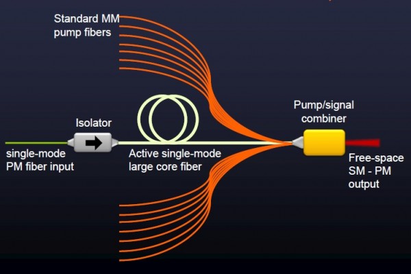
We developed an all-fiber component with a signal feedthrough capable of combining up to 6 fiber-coupled multi-mode pump sources to a maximum pump power of 400 W at efficiencies in the range of 89 to 95%, providing the possibility of transmitting a high power signal in forward and in reverse direction. Hence, the fiber pump combiner can be implemented in almost any fiber laser or amplifier architecture. The complete optical design of the combiner was developed based on ray tracing simulations and confirmed by experimental results.

(N+1)X1 Pump and Signal Combiner

1. Introduction

For the realization of compact, reliable, rugged and efficient monolithic high power fiber laser systems, the efforts of integrating all-fiber components have been increased in recent years [1,2]. A key component of a highly integrated fiber laser or amplifier system is a high power all-fiber signal and pump combiner.

The most common type of fiber combiner, a fused tapered fiber bundle (TFB) [3,4], is based on the fiber end face pumping technique and is probably the most sophisticated pump combiner capable of handling several hundred watts of pump power [5]. A TFB with signal feedthrough consists of a central input signal fiber, guiding the signal light, surrounded by several multi-mode fibers, guiding the pump light, and an output pigtail double-clad (DC) fiber which combines the signal and pump light in a single pigtail fiber. In order to match the diameter of the fiber bundle to the diameter of the output pigtail fiber, the bundle is slowly melted and tapered. After the tapering process the fiber bundle is cleaved around the taper waist and fusion spliced to the output pigtail DC fiber. However, tapering of the fiber bundle inherently involves increasing the numerical aperture (NA) of the pump light and a change of the mode field diameter (MFD) of the signal light. Hence, the necessary optical matching and mechanical alignment requirements between the tapered fiber bundle and the output pigtail DC fiber can lead to several drawbacks of the TFB structure: (1) less flexibility in the choice of input fibers that match the output pigtail DC fiber after the tapering process, (2) a slight mismatch or misalignment between the signal mode field diameters (MFD) of the tapered input signal fiber and the output pigtail DC fiber leads to a degradation of the beam quality, primarily in conjunction with signal insertion loss, and (3) in the case of a backward propagating signal, e.g. for a counter-propagation pumped fiber amplifier, the signal insertion loss (up to 10%) can cause damage to the pump diodes due to their insufficient isolation against amplified signal light.

A more promising approach to overcome these problems is side-pumping technology, which involves coupling the pump light via the outermost cladding surface into the fiber. The key advantage of this technology is the uninterrupted signal core, eliminating the need for an additional fusion splice in conjunction with signal mode matching. In recent years several proposals for side-pumping of DC fibers have been reported, such as V-groove side pumping [6], a mirror embedded in the inner cladding of a DC fiber [7] or side-coupling by an angle polished pump fiber [8]. However, for most of these side-pumping configurations it is difficult to reach the mechanical accuracy required for a stable and efficient pump light coupling.

A more rugged approach is a monolithic all-fiber combiner like the GT-Wave coupler [9], the employment of a tapered capillary around a multi-clad fiber [1011] or direct fusion of one or more tapered multi-mode fibers to the outermost cladding of multi-clad fibers [1214]. In Ref [11] seven pump delivery fibers with a core diameter of 110 µm (NA 0.22) were combined and laterally coupled via a tapered capillary into a DC fiber with a core diameter of 400 µm (NA 0.46), which led to a combined pump power of 86 W with a coupling efficiency of ~80%. In Ref [13], direct lateral fusion of one tapered pump delivery fiber with a core diameter of 200 µm (NA 0.46) to a DC fiber of 250 µm (NA 0.46) led to a coupling efficiency of 90% at a pump input power of 120 W, furthermore, a pump delivery fiber with a diameter of 400 µm (NA 0.46) was used to couple a pump power of 300 W with an efficiency of 85% into a DC fiber with a diameter of 400 µm (NA 0.46). These impressive coupling efficiencies for one pump port were achieved by use of a straight and a tapered fiber section, allowing for highly efficient coupling of pump light rays with a high numerical aperture. Thus, in Ref [13] the impact of the straight fiber section on the side-pump coupling process was discussed. However, a review of the literature reveals that the impact of the fiber and taper parameters on the pump coupling behavior as well as the loss mechanism have not yet been investigated in detail for side-pumped combiners based on direct fusion of one or several tapered multi-mode fibers to the outermost cladding of a DC fiber.

We report detailed simulations and experiments for a component which combines up to 6 multi-mode fibers with a core diameter of 105 µm (NA 0.15 or 0.22) into a DC fiber with a cladding diameter of 250 µm (NA 0.46) via side-coupling. Firstly, we explain the principle of the optical design of the fiber combiner. For a fiber combiner with a single pump port, the achievable pump coupling efficiency and the corresponding loss mechanisms were investigated. For multiple pump ports, the simulations and experiments showed that with each additional pump port, the taper parameters need to be adjusted in comparison to a single pump port configuration. These simulation results can also be used as an estimation for fiber combiners, which combine one or several multi-mode fibers with a core diameter of 200 µm (NA 0.22) into a DC fiber with a cladding diameter of 400 µm (NA 0.46). Therefore, this work covers two important fiber combiner types, since active fibers with cladding diameters of 250 or 400 µm are typical sizes provided by fiber manufacturers and used for continuous wave and pulsed laser systems. In addition, we also investigated the signal feedthrough of the combiner. We demonstrated a low signal insertion loss, maintenance of an excellent signal beam quality and an efficient isolation of the pump diodes against signal light in the case of a reverse propagating signal. The preservation of the signal light properties by the fiber combiner was utilized in Ref [15] for the realization of a counter-propagation pumped single-frequency fiber amplifier with an amplified signal power of 300 W.

Comparation Between EPON and GPON

With the continuous progress of science and technology, the Internet has gradually gone into the homes of the ordinary people, and the speed of broadband has increasingly become the topic of people in the entertainment and work often, from narrowband dial-up to broadband Internet, and then the fiber access Internet, broadband network, the rapid pace of PON technology gradually come to the front. Currently, there are two quite compelling PON standard has been officially released, which are GPON standard developed by the ITU / FSAN and EPON standard developed by IEEE 802.3ah working group. PON technology has been no doubt the ultimate solution for the future FTTH era. EPON and GPON who will the dominant FTTH tide has become a new hot debate. What’s the difference between EPON and GPON?

GPON and EPON Differences

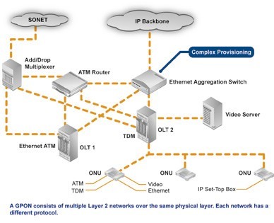
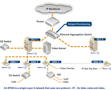
Perhaps the most dramatic distinction between the two protocols is a marked difference in architectural approach. GPON provides three Layer 2 networks: ATM for voice, Ethernet for data, and proprietary encapsulation for voice. EPON, on the other hand, employs a single Layer 2 network that uses IP to carry data, voice, and video.

A multiprotocol transport solution supports the GPON structure (Figure 1). Using ATM technology, virtual circuits are provisioned for different types of services sent from a central office location primarily to business end users. This type of transport provides high-quality service, but involves significant overhead because virtual circuits need to be provisioned for each type of service. Additionally, GPON equipment requires multiple protocol conversions, segmentation and reassembly (SAR), virtual channel (VC) termination and point-to-point protocol (PPP).

Figure 1: Diagram showing a typical GPON network.

EPON provides seamless connectivity for any type of IP-based or other “packetized” “communications” (Figure 2). Since Ethernet devices are ubiquitous from the home network all the way through to regional, national and worldwide backbone networks, implementation of EPONs can be highly cost-effective. Furthermore, based on continuing advances in the transfer rate of Ethernet-based transport — now up to 10 Gigabit Ethernet — EPON service levels for customers are scalable from T1 (1.5 Mbit/s) up through 1 Gbit/s.

Figure 2: Diagram showing a typical EPON network.

Upstream Bandwidth

Subtracting the various system run overhead from the total bandwidth of the system uplink transmission is the upstream available bandwidth. It has a great relationship with the number of the ONU contained in the system, DBA (Dynamic Bandwidth Allocation) algorithm polling cycle, the type of bearer services, as well as the various business proportion. EPON and GPON are broadband access technology, hosted business IP data services. Below we will calculate the uplink the beared pure IP services available bandwidth of EPON and GPON that contain 32 ONUs, fiber optic coupler,the case of polling period 750s.

EPON

EPON upstream rate is 1.25 Gbit/s. Because the 8B/10B line coding, each 10bit are 8bit valid data, so its effective upstream transmission bandwidth is 1 Gbit/s. EPON upstream overhead of running the system and its proportion of the total bandwidth are as following:

1. Used for the the burst reception of physical layer overhead: about 3.5%;

2. Ethernet frame encapsulation overhead: about 7.4%;

3. MPCP (Multi-Point Control Protocol) and OAM operation and management of maintenance protocol overhead: about 2.9%;

4. DBA algorithm resulting in the remaining time slots (that is not sufficient to transfer a complete Ethernet frame time slot) wasted: about 0.6%;

5. EPON upstream total overhead is all of the above about 144 Mbit/s, the available bandwidth is about 856 Mbit/s.

GPON

GPON supports a variety of rate levels, has asymmetric rate that downlink is 2.5Gbps or 1.25Gbps, the upgoing is 1.25Gbps or 622 Mbps. NRZ encoding the uplink total bandwidth for 1.244 Gbit/s, GPON upstream overhead of running the system as following:

1. The proportion of its total bandwidth is used for the the burst reception of physical layer overhead: about 2.0%;

2. GEM (GPON encapsulation method) frame and the Ethernet frame encapsulation overhead: about 5.8%;

3. The PLOAM (physical layer operation, management and maintenance) protocol overhead: about 2.1%;

4. Remaining slots of the DBA algorithm introduced the additional encapsulation overhead: about 0.8%.

5. GPON upstream total overhead is all of the above about 133 Mbit/s, the available bandwidth about 1111 Mbit/s.

Relative Terms In PON System

ODN (Optical Distribution Network)

ODN is a FTTH fiber optic cable network based on PON equipment. Its role is to provide optical transmission channel between the OLT and ONU. Accroding the function, ODN from the central office to the client can be divided into four parts: feeder fiber optic subsystems, cable wiring subsystem, home line of fiber optic subsystems and fiber terminal subsystems. The main components in ODN include optical fibers, optical connectors, optical splitters and corresponding equipments for installing them.

OLT (Optical line terminal)

OLT is a terminal equipment connected to the fiber backbone. It sends Ethernet data to the ONU, initiates and controls the ranging process, and records the ranging information. OLT allocates bandwidth to the ONU and controls the starting time and the transmission window size of the ONU transmission data.

ONU (Optical network unit)

ONU is a generic term denoting a device that terminates any one of the endpoints of a fiber to the premises network, implements a passive optical network (PON) protocol, and adapts PON PDUs to subscriber service interfaces. In some contexts, ONU implies a multiple subscriber device. Optical Network Terminal (ONT) is a special case of ONU that serves a single subscriber.

APON / BPON

APON (ATM PON) is the first PON system that achieved significant commercial deployment with an electrical layer built on Asynchronous Transfer Mode (ATM). BPON (Broadband PON) is the enhanced subsequence of APON, with the transmission speed up to 622Mb/s. At the same time, it added the dynamic bandwidth distribution, protection and other functions. APON/BPON systems typically have downstream capacity of 155 Mbps or 622 Mbps, with the latter now the most common.

GPON

GPON (Gigabit PON) is based on the TU-TG.984.x standard for the new generations of broadband passive optical access. Compared with the other PON standards, GPON provides the unprecedented high bandwidth downlink rate of up to 2.5 Gbit/s, the asymmetric features better adapt to the broadband data services market. It provides the QoS full business protection, at the same time carries ATM cells and (or) GEM frame, the good service level, the ability to support QoS assurance and service access. Carrying GEM frame, TDM traffic can be mapped to the GEM frame, 8kHz using a standard frame able to support TDM services. As a carrier-grade technology standards, GPON also provides access network level protection mechanism and full OAM functions. GPON is widely deployed in FTTH networks. It can develop into two directions which is 10 GPON and WDM-PON.

WDM-PON

WDM-PON uses wavelength division multiplexing technology to access to the passive optical network. It has four programs as following:

1. Each ONU is assigned with a pair of wavelength, for uplink and downlink transmission, thereby providing the OLT to each ONU fixed virtual point-to-point bidirectional connections.

2. ONU uses tunable lasers, according to the needs of the ONU to dynamically allocate the wavelength, and each ONU can be shared the wavelength, the network are reconfigurable.

3. Using colorless ONUs, the ONU are independent from the wavelength.

4. Using a combination of TDM and WDM technology, Composite PON (CPON). CPON uses WDM technology in the downstream, and TDMA technology in the upstream.

EPON / GEPON

EPON (Ethernet PON) is the rival activity to GPON which uses Ethernet packets instead of ATM cells. GEPON uses 1 gigabit per second upstream and downstream rates. It is a fast Ethernet over PONs which are point to multipoint to the premises (FTTP) or FTTH architecture in which single optical fiber is used to serve multiple premises or users. EPON is an emerging broadband access technology, through a single fiber-optic access system, to access the data, voice and video service, and it has a good economy.

What is Passive Optical Network?

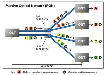
Passive Optical Network (PON) is a form of fiber-optic access network that uses point-to-multipoint fiber to the premises in which unpowered optical splitters are used to enable a single optical fiber to serve multiple premises. A PON system consists of an OLT at the service provider’s central office and a number of ONU units near end users, with an ODN between the OLT and ONU. PON reduces the amount of fiber and central office equipment required compared with point-to-point architectures.

PON Optical Network
Passive Optical Network (PON)

The most obvious advantage of the PON network is the elimination of the outdoor active devices. All the signals processing functions are completed in the switches and the user premises equipment. The upfront investment of this access methods are small, and the most funds investment is postponed until the user really access. Its transmission distance is shorter than the active optical access system. The coverage is also smaller, but it is low cost, no need to set the engine room, and easy to maintain. So this structure can be economically serve for the home users.

PON Development Background

Seen from the entire network structures, due to the larger numbers of laying optical fibers, and widely applications of DWDM technology, the backbone network has been a breakthrough in the development. The same time, due to advances in Ethernet technology, its dominant LAN bandwidth has increased from 10M, 100M to 1G or 10G.. At present, what we are concerned about is the part between the network backbone and local area networks, home users; this is often said that the “last mile”, which a bottleneck is. Must break this bottleneck, may user in the new world of the online world. It is as if in a national highway system, trunk and regional roads have been built in the broad high-grade highway, but leads to the families and businesses of the door was still narrow winding path, the efficiency of the road network cannot play.

What is OADM? How much do you know?

The OADM, or optical add drop multiplexer, is a aperture into and out of a distinct approach fiber. In practice, best signals canyon through the device, but some would be “dropped” by agreeable them from the line. Signals basic at that point can be “added” into the band and directed to addition destination. An OADM may be advised to be a specific blazon of optical cross-connect, broadly acclimated in amicableness analysis multiplexing systems for multiplexing and acquisition cilia optic signals. They selectively add and bead alone or sets of amicableness channels from a close amicableness analysis multiplexing (DWDM) multi-channel stream. OADMs are acclimated to bulk finer admission allotment of the bandwidth in the optical area actuality anesthetized through the in-line amplifiers with the minimum bulk of electronics.

OADM Module
CWDM and DWDM OADM

OADMs accept acquiescent and alive modes depending on the wavelength. In acquiescent OADM, the add and bead wavelengths are anchored advanced while in activating mode, OADM can be set to any amicableness afterwards installation. Acquiescent OADM uses Filter WDM, cilia gratings, and collapsed waveguides in networks with WDM systems. Activating OADM can baddest any amicableness by accessories on appeal after alteration its concrete configuration. It is additionally beneath big-ticket and added adjustable than acquiescent OADM. Activating OADM is afar into two generations.

A archetypal OADM consists of three stages: an optical demultiplexer, an optical multiplexer, and amid them a adjustment of reconfiguring the paths amid the optical demultiplexer, the optical multiplexer and a set of ports for abacus and bottomward signals. The optical demultiplexer separates wavelengths in an ascribe cilia assimilate ports. The reconfiguration can be accomplished by a cantankerous affix console or by optical switches which absolute the wavelengths to the optical multiplexer or to bead ports. The optical multiplexer multiplexes the amicableness channels that are to abide on from demultipexer ports with those from the add ports, assimilate a distinct achievement fiber.

Physically, there are several means to apprehend an OADM. There are arrays of demultiplexer and multiplexer technologies including attenuate blur filters, cilia Bragg gratings with optical circulators, changeless amplitude annoying accessories and chip collapsed arrayed waveguide gratings. The switching or reconfiguration functions ambit from the chital cilia application console to a array of switching technologies including micro-electro automated systems (MEMS), aqueous clear and thermo-optic switches in collapsed waveguide circuits.

CWDM and DWDM OADM accommodate abstracts admission for average arrangement accessories forth a aggregate optical media arrangement path. Regardless of the arrangement topology, OADM admission credibility acquiesce architecture adaptability to acquaint to locations forth the cilia path. CWDM OADM provides the adeptness to add or bead a distinct amicableness or multi-wavelengths from a absolutely multiplexed optical signal. This permits average locations amid alien sites to admission the common, point-to-point cilia bulletin bond them. Wavelengths not dropped pass-through the OADM and accumulate on in the administration of the alien site. Additional called wavelengths can be added or alone by alternating OADMS as needed.

DK Photonics provides a wide selection of specialized OADMs for WDM system. Compact CWDM module and custom WDM solutions are also available for applications beyond the current product designs including mixed combinations of CWDM and DWDM.

2018 global optical networking market will reach $ 17.5 billion

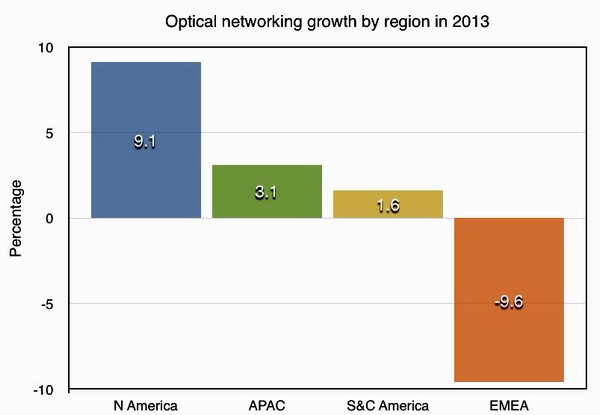
Market research firm Ovum, said a new optical network investment cycle is happening in addition to EMEA (Europe, Middle East, Africa) outside of all regions. Currently still dominate the market growth in North America, and the Asia-Pacific regions are also increasing investment spending, South and Central America is also true, but in 2013 the EMEA region again declined.

Ovum predicts that by 2018 the global optical networking market will reach $ 17.5 billion, the forecast period CAGR of 3.1%.

Unchanged after two consecutive years, 2013 North American optical networking market spending will grow 9.1%. Currently, in North America a service providers and cable operators are investing in the core network to the network can meet the needs of all types of traffic, in this area is also being deployed 100G.

In contrast, in the EMEA region, 2013 year optical network market shrank by nearly 10%. As in Europe, there is no corresponding expenses incurred in the EMEA region is leading the market decline.

optical network market

100G become major trends:

Ovum said that in the EMEA region, the optical networking market in the past five years, spending four years in a decline in its lack of investment and the current phenomenon of more and more serious. However, service providers are expanding their networks, and a chronic lack of investment spending in the region will eventually happen.

2013, we have seen large-scale WDM systems selected 100G. And 100G sales are increasing; currently 100G spending has more than 40G.

MPO/MTP Fiber Cables Data Center Applications

MPO/MTP Fiber Cable is offered for various applications for all networking and device needs like 100 Gig modules. It uses a high-density multi-fiber connector system built around precision molded MT ferrule. DKComm’s MPO fiber cables are available in UPC and APC finishes, support both multimode and single mode applications, and optional lengths available. Our MPO/MTP fiber cable is with push connector IEC 61754-7 and TIA/EIA 604-5A compliant and offer low cost per termination for high density applications. The MPO/MTP fiber cables are tested with guaranteed quality, and they can be installed easily, which saves time and money.

MPO/MTP Standard Trunk Cables

There are three types package MTP/MPO Cables: MPO/MTP Standard Trunk Cables, MPO/MTP Hybrid Trunk Cables, MPO/MTP Harnesses Cables and MPO/MTP Cassettes.

MPO/MTP Standard Trunk Cables

The MPO/MTP Trunk cable is designs for Data Center Applications. It is divided into round cable and flat cable with the outer diameter of 3.0 mm or 4.5 mm. The connector where this cable is terminated on is the so called MPO/MTP connector. All of MPO/MTP fiber optic patch cables are 100% optically tested for maximum performance. We have all lengths and connectors available.

DKComm offer singlemode and multimode (OM1, OM2, 10G OM3, 10G OM4) MPO/MTP Cable. Singlemode MPO/MTP cable is primarily used for applications involving extensive distances, 10G MPO/MTP cable provide 10 gigabit data transfer speeds in high bandwidth applications and they are 5 times faster than standard 50um fiber cable. Work with both VCSEL laser and LED sources. The meanwhile, we also provide 40G/100G MPO/MTP trunk cable.

MPO/MTP Hybrid Trunk Cables

DKComm’s MPO / MTP Hybrid Trunk Cable are available in SM (9/125), MM (50 or 62.5/125), 10Gig fiber types. You could select the corning fiber according to your own needs with the selection of 12/24 fiber cores. The cable is MPO/MTP on one end, with single-fiber connectors on another end, single-fiber connector interface available in SC, ST, LC, MTRJ in forms of Simplex or Duplex channeling. The fiber splitters are available in both plastic and metal fiber splitter, which give you various selections.

MPO/MTP Harnesses Cables

DKComm’s MPO/MTP harnesses cables are usually divided into three types of MPO/MTP-MPO/MTP connector, MPO/MTP-Common connector, MPO/MTP-Secure Keyed LC connector and 40G/100G MPO/MTP

Harnesses cable, according to different colors divided into SM, MM and 10G MM, you could select the corning fiber according to your own needs with the selection of 8/12/24 fibers.

The MPO/MTP Harnesses cables differs from Trunk cables, it works from trunk backbone assemblies to fiber rack system, and the trunk cable is high density back bone cabling. The MPO/MTP harnesses cable application for data centers requiring quick infrastructure deployment with extended reach that want to maintain bandwidth throughout the infrastructure, it design cater for up-scaling needs and future technologies growth, it’s the best solution, which covers all fiber optic cabling needs in all areas of Data Center.

MPO/MTP Cassettes

MPO fiber optic cassette, with SC,LC,ST, FC connectors, is a highly flexible fiber management unit that can be used stand alone or integrated into the MPO fiber optic patch panels. DKComm supply high quality MPO cassette which is designed to reduce installation time and cost for an optical network infrastructure in the premises environment. We are direct manufacturer of the MPO fiber optic cassette, that also supply rack chassis like 1U 19” rack for putting more MPO LGX cassettes.

More Information about Data Center Applications:

http://www.dk-fiberoptic.com/solution/data-centre-solution.html

What is Pump Laser Protector, Where is the Pump Laser Protector use?

The Pump Laser Protector (also called Pump Protection Filters) is a passive component which allows maximum transmission from a discrete fibre-coupled pump laser diode and blocks parasitic signals around the centre wavelength of the laser from being reflected back into the laser.

Pump Laser Protector
Multimode Pump Laser Protector -10~30W

Single-emitter laser diodes are highly regarded for their long term reliability. However, these devices are very sensitive to backward propagating light within the delivery fiber. Backward power imaged onto the diode material, as small as 5% of the pump diode output, can cause accelerated diode degradation and, in the majority of cases, catastrophic failure.That is why we need Pump Laser Protector.

DK Photonics offers filter technology that provides protection to pump diodes under these conditions (up to 50 dB Backward Signal Attenuation). Splicing these filters to the pump output fiber rejects unwanted light before it reaches the diode.

Multimode Pump Protection filters are available for a wide range of standard light emitting diodes. Fiber pigtails are 105/125 micron, with both 0.15 and 0.22 NA cores and 50/125 or 62.5/126 MM fiber available. Operating wavelengths cover the majority of diode laser lines (915 nm, 940 nm, 960 nm and 976) and maximum power handling is 25W without water-cooling.DK Photonics recently released a new type of Pump Laser Protector up to 200W handling power with water-cooling technology. And also have SingleMode Pump Laser Protector with Hi1060 fiber for 976nm fiber laser.

If you do not see a Pump Laser Protector from the standard configurations that meets your needs, we welcome the opportunity to review your desired specification and quote a filter best suited to your application. Different pump/rejection wavelengths or fiber pigtail can be accommodated.

DK Photonics – www.dkphotonics.com specializes in designing and manufacturing of high quality optical passive components mainly for telecommunication, fiber sensor and fiber laser applications,such asDK Photonics' promotion products including:High Power Isolator,1064nm Components,PM Components,Pump Combiner,Pump Laser Protector,which using for fiber laser applications.Also have Mini-size CWDM, Optical Circulator, PM Circulator,PM Isolator, Fused Coupler,Mini Size Fused WDM.More information,please contact us.

Introduction for CWDM MUX+DEMUX Module 8/16 Channels Dual Fiber with 1U 19 Rack Mount Box

Why do we choose CWDM MUX/DEMUX solution?

CWDM Mux/Demux is a flexible, low-cost solution that enables the expansion of existing fiber capacity. The CWDM Mux/Demux lets operators make full use of available fiber bandwidth in local loop and enterprise architectures. DK Photonics’ CWDM Mux/Demux is a universal device capable of combining up to 18 optical signals into a fiber pair or single fiber. It is designed to support a broad range of architectures, ranging from scalable point-to-point links to two fiber-protected rings. The important advantage of CWDM solution is the cost of the optics which is typically 1/3rd of the cost of the equivalent DWDM optics.

Description:

DK Photonics CWDM MUX+DEMUX Module 8/16 Channels (Dual Fiber) with 1U 19 Rack Mount Box utilize thin film coating technology and proprietary design of non-flux metal bonding micro optics packaging. Our 8CH CWDM Mux and Demux dual fiber 1U 19 Rack Mount Box support ITU-T G.694.2 wavelengths between 1270nm to 1610nm in 20nm increments. (Note: The ITU standard specifies the exact center of 8/16CH CWDM Mux and Demux dual fiber 1U 19 Rack Mount Box wavelength as 1531nm, 1591nm, 1611nm, etc. However, for clarity (and to comply with general industry conventions) the text in this data sheet refers to these wavelengths as 1530nm, 1590nm, 1610nm, etc.) 8/16 Channel CWDM Mux and Demux dual fiber 1U 19 Rack Mount Box are protocol and rate transparent allowing different services up to 10Gbps to be transported across the same fiber link. It allows for any protocol to be transported over the link, as long as it is at a specific wavelength (i.e. T1 over fiber at 1570nm transported alongside 10Gbps Ethernet at 1590nm). This allows for long-term future proofing of the networking infrastructure because the multiplexers simply refract light at any network speed, regardless of the protocol being deployed.

Our CWDM Mux/Demux can support up to 18 wavelengths between 1270nm to 1610nm in 20nm increments when com fiber is ITU-T G.694.2 , however if com fiber is ITU-T G.652, we recommend adopt 1270nm and 1290nm instead of 1390nm and 1509nm because of water peak loss.

DK Photonics’ provides a complete portfolio of CWDM Mux Demux and Optical Add Drop Multiplexer (OADM) units to suit all applications such as:- Gigabit & 10G Ethernet, SDH/SONET, ATM, ESCON, Fibre Channel, FTTx and CATV.

8/16 channel CWDM MUX+DEMUX in point to point application

Key Features

  • Up to 18 channels over 2 fibers
  • MUX and DEMUX combined 1U
  • Optical interfaces support all protocols from 30Mbps to 10Gbps, including OC-3/STM-1, OC-12/STM-4, OC-48/STM-16, OC-192/STM-64, Gigabit Ethernet SX, Gigabit Ethernet LX, Fast Ethernet, FDDI, ATM, ESCON, FICON, Fiber Channel, Coupling Link, 10G Ethernet
  • Distance up to 120km, based on used CWDM SFP+, CWDM XFP, CWDM X2, CWDM XENPAK, CWDM SFP, CWDM GBIC transceivers
  • Any configuration on demand
  • Your choice of adapter: SC, LC, E2000, MU etc
  • 19” 1U size or other according to customer requirements
  • For Central Office or Outside Plant
  • Compliant to ITU-T G.694.2 CWDM standard
  • ISO 9001 manufacturing facility
  • Fully transparent at all data rates and protocols from T1 to 40 Gbps
  • Completely passive, no power supply needed
  • Simple to install, requires no configuration or maintenance
  • Low-cost transceivers applicable, existing equipment can still be used

Applications

  • All Enterprises and Carrier with Fiber Optic Infrastructure
  • Transmit additional applications via existing lines
  • Connect buildings to CWDM campus ring
  • Connect Field offices to central office
  • Ideal solution for metro-core, metro-access and enterprises

DK Photonics’ 1RU Rack-mount chassis are made by best which can protect CWDM MUX/DEMUX inside well. These Low profile modular designs are widely used in computer centers, center office, IDC, OLT and FDC etc.