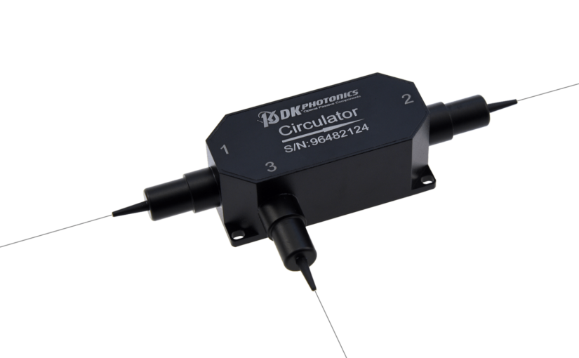
What are the Technical Specifications of the 1064 High Power Circulator?

A three-port device that directs optical signals from one port to another in a specific order is known as a circulator.  The difference between a circulator and a high-power circulator is that the latter handles the high-power optical signals. The high-power circulators are used in the high-power handling applications. Such applications are laser systems, fiber amplifiers and optical communication systems.

Other than this, the high-power circulator separates the incoming and outgoing optical signals while reducing any signal loss. Also, it increases network performance and efficiency.

In modern optical networks, a high-power circulator is very crucial. But, people don’t use it as designed because they are aware of its technical specifications. In this post, we will discuss the technical specifications of a high power circulator, focusing on the 1064nm high-power circulator.

Most common wavelength 

As the most common wavelength for high-power circulators, 1064nm wavelength is in the near-infrared region. It is commonly used in optical fiber communication systems. The technical specifications of 1064nm high-power circulators are based on different factors, such as power handling, insertion loss and polarization dependence.

Power handling

One of the most critical technical specifications is power handling, which refers to the maximum power that the circulator can handle without experiencing damage. Typically, the power handling capacity of a circulator is measured in watts. As it’s about the 1064nm high power circulators, the power handling capacity can range from a few watts to several hundred watts. The exact power handling capacity depends on the design and construction of the circulator.

Insertion loss

Another critical technical specification of high-power circulators is Insertion loss. It refers to the amount of optical power lost when the signal passes through the circulator. Insertion loss is typically measured in decibels (dB), and lower insertion loss is always preferred as it leads to higher system efficiency. The insertion loss of 1064nm high-power circulators can vary depending on the specific design and construction of the circulator.

Polarization dependence 

An important technical specification of high-power circulators is polarization dependence. It refers to the sensitivity of the circulator to the polarization of the incoming signal. A circulator that is polarization dependent will have different insertion loss values for different polarizations of light. The polarization dependence of 1064nm high-power circulators can vary, but it is typically in the range of a few tenths of a dB.

Isolation between ports 

Isolation between ports is another critical technical specification of high-power circulators. Isolation is the measure of how much power is coupled from one port to another port. A high level of isolation between ports is desirable as it ensures that signals do not interfere with each other. The isolation of 1064nm high-power circulators can vary depending on the specific design and construction of the circulator.

Physical dimension

Last but not the least, the physical dimensions of the circulator are also important technical specifications. The size and weight of the circulator can have an impact on the overall design of the optical system. The physical dimensions of 1064nm high-power circulators can vary depending on the specific design and construction of the circulator.

The performance of optical systems depends on the technical specifications of 1064nm high-power circulators. Some of the most important technical specifications that need to be considered when selecting a high-power circulator are power handling, insertion loss, polarization dependence, isolation, and physical dimensions are.

The specific technical specifications of a circulator vary depending on the application and the requirements of the optical system. So, to ensure optimal performance and efficiency in optical systems, it is important to carefully consider the technical specifications of high-power circulators

If you are looking for 1064nm high-power circulators, come to DK Photonics.
The Need and Importance of Polarization Maintaining Optical Isolator

In today’s fast-paced technological world, the data transmission is of utmost importance. So, the use of optical fibers has become ubiquitous. Compared to traditional copper wires, the optical fibers offer higher data transfer rates and a more reliable means of communication. But like any technology, there are challenges. One of the challenges is the polarization-dependent loss (PDL). Polarization Maintaining Optical Isolators (PMOIs) play an important role in minimizing PDL in optical fibers.

What do you understand with Polarization Dependent Loss (PDL)?

Polarization dependent loss (PDL) is a scientific approach that occurs the time when polarization of an incoming light signal changes while passes through an optical fiber. When the polarized incoming signal is orthogonal to the preferred polarization axis of the fiber, the transmission loss is higher. This happens because the signal energy couples to other modes that aren’t aligned with the fiber’s preferred polarization axis. Due to this loss, there is a significant impact on the overall performance of the optical fiber communication system, reducing its efficiency and reliability.

What is a Polarization Maintaining Optical Isolator?

A Polarization Maintaining Optical Isolator is an optical device, allowing light to pass in only one direction while isolating the back-reflected light. The isolator consists of a Faraday rotator, a polarizer, and an input/output fiber. The role of a Faraday rotator is to rotate the polarization of the incoming light signal by 45 degrees. Regarding a polarizer, it only allows light with the preferred polarization axis to pass through, while blocking the light with orthogonal polarization. As the backward reflected light is rotated by the Faraday rotator, its polarization is orthogonal to the preferred axis. So, it gets blocked by the polarizer. This is how Polarization Maintaining Optical Isolator protects optical fiber communication systems from PDL caused by back-reflected light.

What’s the importance of Polarization Maintaining Optical Isolators?

Polarization dependent loss is a significant problem, impacting the performance of optical fiber communication systems. This increases a bit error rates, reduces signal-to-noise ratio, and decreases transmission distance. Polarization Maintaining Optical Isolators are a crucial component in minimizing PDL, maintaining the efficiency and reliability of optical fiber communication systems.

Polarization Maintaining Optical Isolators are commonly used or integrated in applications that require high precision. These applications include a medical equipment, scientific research, and military communication systems. If there is any data loss in these applications, it becomes critical and has severe consequences. The isolators make sure that the data is transmitted accurately and with reliability, which make them an essential component of these systems.

Other than this, Polarization Maintaining Optical Isolators are used in fiber optic gyroscopes. The gyroscopes are used in navigation systems in airplanes, ships, and spacecraft. They require high precision and reliability as any errors can have severe consequences. Polarization Maintaining Optical Isolators minimize Polarization dependent loss. This improves the accuracy and reliability of fiber optic gyroscopes.

The use of optical fibers has become ubiquitous in today’s fast-paced technological world as they offer a more reliable means of communication than traditional copper wires. But, these optical fibers also pose challenges, including polarization-dependent loss (PDL).  This impacts the performance of optical fiber communication systems.

Polarization Maintaining Optical Isolators minimize polarization-dependent loss and ensure the efficiency and reliability of these systems. They are especially used in applications that require high precision and reliability, such as in medical equipment, scientific research, and military communication systems. Other than this, they are used in fiber optic gyroscopes, which are used in navigation systems in airplanes, ships, and spacecraft. Also, they ensure accurate and reliable data transmission. It’s expected that importance of Polarization Maintaining Optical Isolators will only increase with the growing use of optical fibers in various applications.

Basics of DWDM Mux/Demux: Working and Its Types

DWDM is an acronym for Dense Wavelength Division Multiplexing. DWDM refers to a laser technology that combines certain optical wavelengths that can be transmitted over a single fiber. The use of DWDM technology helps in increasing the bandwidth of an existing fiber-optic network and allows the transmission of signals of several wavelengths simultaneously.

In any DWDM system, there are two important components called Mux (Multiplexer) and Demux (Demultiplexer). In this blog, we will help you understand the working of DWDM Mux/Demux by explaining how mux and demux work in a DWDM system.

What is a DWDM Mux/Demux?

To understand DWDM Mux/Demux, you will need to know what exactly DWDM is. To be precise, Dense Wavelength Division Multiplexing (DWDM) is an optical wavelength multiplexing technology that allows you to expand the bandwidth capacity of an existing fiber optic network.

The data streams coming from different sources are combined or multiplexed together on an optical fiber, wherein each signal travels at the same speed on its own wavelength.

In a DWDM system, a multiplexer is a module located at the transmitter end where several data signals are combined and transmitted over a single fiber, while a demultiplexer is a module at the receiver end where combined data signals are split and each signal is passed through a separate channel to an optical receiver.

As a result, a DWDM Mux/Demux module is designed to multiplex several DWDM channels into one or two fibers. DWDM mux/demux systems not only extend the fiber optical network’s bandwidth but also lower the cost, making them an ideal network solution for data transmission.

How does DWDM Mux/Demux work? What is its working principle?

In DWDM network architecture, the structure starts with transceivers that accept data input from a range of traffic types and protocols. This transceiver or forwarder performs the mapping of input data to a separate DWDM wavelength. Each individual wavelength carrying different kinds of data is fed into a multiplexer. The multiplexer filters and combines multiple wavelengths onto a single output port for transmission via the main DWDM fiber.

At the receiving end, the combined wavelengths are isolated and restored to their original form with the help of a demultiplexer. Each wavelength is separated and passed onto a separate channel, which is then routed to the respective client-side output through additional wavelength-matched transponders or transceivers.

What are the different types of DWDM Mux/Demux?

DWDM Mux/Demux can be divided into two types:

  • Active DWDM mux/demux
  • Passive DWDM mux/demux

The DWDM mux/demux that needs a power supply is called an active DWDM mux/demux. However, the one that doesn’t need a power supply is called passive DWDM mux/demux.

Active DWDM Mux/Demux

An active DWDM mux/demux consists of a wavelength-adjustable laser, wavelength-adjustable filter, and wavelength-selective amplifier. It provides you more control over the optical network where you can dynamically re-tune wavelengths without dropping connections. It is mainly used in large-capacity optical transmission applications.

Passive DWDM Mux/Demux

A passive DWDM mux/demux is an unpowered, pure optical equipment that requires zero maintenance, upgrades, or power to function. It consists of a dispersion device, interference device, optical coupler, and more. It is simple to use and is typically used in the access layer of MAN, campus network, enterprise network, etc.

Are you looking for DWDM Mux/Demux for your application? If yes, connect with DK Photonics today.

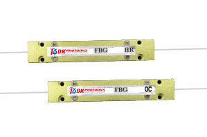
What is a Fiber Bragg Grating Array: Applications and Benefits

Fiber Bragg Gratings arrays are designed for strain and temperature measurement.

Fiber Bragg  Gratings written within optical fibers offer great resolution and robustness, making them perfect for temperature or mechanical strain monitoring applications. Real-time safety and function monitoring is becoming increasingly important in areas ranging from transportation, aviation, and aerospace to civil engineering and oil and gas. This technology can be used to monitor strain in a concrete structure, the movement of an aircraft wing, the detection of pipeline leaks, and so on.

Applications of FBG Array

Fiber Bragg Gratings (FBGs) are outstanding sensor elements that can measure temperature, strain, pressure, tilt, displacement, acceleration, load, and the presence of different industrial, biomedical, and chemical compounds in both static and dynamic modes of operation. In addition, the FBG is a superb signal-shaping and filtering element for a wide range of applications. FBG array is used in the following industries:

  • Geotechnical and civil engineering
  • Electricity production, conversion, and storage
  • Transportation for commercial purposes
  • Vessels, vehicles, and equipment with high performance
  • Security and perimeter surveillance
  • Medical and biotechnology
  • Industrial
  • Industrial
  • Research and development

The Advantages of FBG Array

A Bragg grating, as a fiber optic sensor, has all of the benefits typically associated with these devices, such as low loss relative to fiber length, immunity to electromagnetic and radio frequency interference, small size and weight, intrinsically safe operation in hazardous material environments, high sensitivity, and long-term reliability. Furthermore, Fiber Bragg grating technology demonstrates an inherent serial multiplexing capability as well as the potential to deliver absolute measurements without the use of referencing.

Operation

The FBG will serve as a wavelength-selective mirror as a resonant structure; it is a narrow-band filter. This means that if light from a broadband source is introduced into the optical fiber, the grating will back-reflect only light with an extremely limited spectral width centered on the Bragg wavelength. The leftover light will travel without interruption via the optical fiber to the next Bragg grating.

Acting as a strain sensor

An FBG has special properties that allow it to function as a sensor. The FBG, for example, will measure strain when the fiber is stretched or compressed. This occurs because optical fiber deformation changes the period of the microstructure and the Bragg wavelength.

Serving as a temperature sensor

A Fibre Bragg grating is also temperature sensitive. The shift in the silica refraction index caused by the thermo-optic effect is the main contributor to the Bragg wavelength change in this scenario. The thermal expansion also affects the period of the microstructure. However, because of silica’s low coefficient of thermal expansion, this effect is minor.

Multiplexing

One of the primary benefits of this technology is its inherent multiplexing capabilities. Hundreds of fiber Bragg gratings can be inscribed on a single optical fiber, which can be as near as a few millimeters apart or as far apart as a few kilometers. Each of these microstructures can be made responsive to parameters other than temperature or strain with suitable packaging.

It is critical to note that all of the sensors can be addressed by a single light source. Furthermore, as long as enough spectral band of the light spectrum is reserved for each sensor, the addition of more and more sensors on the same fiber results in relatively small loss and no crosstalk.

The FBG Array is a collection of Bragg gratings inscribed on a single optical cable. It can handle long-term monitoring as well as multi-point monitoring. It can improve system stability and reliability while also simplifying the system. Contact DK Photonics to personalize the FBG array according to you.

5G and Fiber Optics: The Next Digital Revolution

We all are hearing about the onset of 5G networks. 5G comes with the promise to connect people and things via intelligent networks and apps and transform the way we live and work. All of this is going to generate massive amounts of data and 5G is the solution to achieve the highest possible performance.

However, before 5G becomes possible around the world, we need to build the network infrastructure to accommodate billions of devices and enormous amounts of traffic that will be sent over the network.

In this blog, we will see how 5G spurs the demand for fiber optics even more. What role do passive optical components play in making 5G possible?

How does 5G spur the demand for fiber optics even more?

An increasing number of new applications and users demand high data rates. It increases data traffic at a rate of more than 50 percent per year per head. Besides, the emergence of new technologies, such as Internet of Things (IoT) and virtual reality (VR) will accelerate the demand for high data rates more than ever. To address this challenge, 5G is being introduced.

5G networks use different optical technologies and concepts, such as a radio-over-fiber (RoF) network, passive optical network (PON), light fidelity (Li-Fi), optical millimeter wavelength bridge, etc. to achieve high data rate and capacity.

A Passive Optical Network (PON) is a fiber optic network to deliver broadband network access to end-customers. It uses ans architecture that implements a point-to-multipoint topology in which a single optical fiber serves multiple endpoints by utilizing passive optical splitters – one of the most common passive optical components in the fiber optic communication industry.

Besides, an optical network utilizes a range of optical passive components, including branching components, such as DWDMs, optical isolators, optical circulators, and optical filters.

Since 5G needs Passive Optical Networks to meet a variety of challenges, it is natural for optical passive components to increase in demand.

How do optical networks help 5G implementation?

Optical network technologies are emerging as one of the most promising solutions to address and eliminate different challenges encountered in 5G communication networks. The main challenge of the 5G network is to facilitate access to information when, where, and in what format we need it. Optical and wireless technologies are being used as pillars in 5G implementation.

While optical fiber cannot go everywhere, it provides a huge amount of bandwidth where it can be implemented, which solves the speed and capacity problems in the 5G network. According to experts, the best approach to make 5G possible is to integrate an optical fiber network and a wireless network. This approach is called Radio over Fiber (RoF) network.

Besides, in addition to the millimeter wave band of wavelength 1mm – 10mm, the optical wave band from wavelength 390nm to 750nm is also considered very promising for 5G communication. Flex-grid optical network is also emerging as a promising network technology for 5G communication systems, which uses sliceable bandwidth variable transceivers, bandwidth variable optical cross connectors, optical splitters and combiners, and bandwidth variable wavelength select switches.

If you need optical passive components to implement passive optical networks for 5G, contact DK Photonics now.

What is an optical circulator in fiber optics? What is it used for?

An optical circulator is a passive multi-port optical component characterized by its non-reciprocal property. It works by keeping the reflected light from coming back to the source and allows this light to pass through the subsequent port, where this light is either absorbed or used. This component is designed in such a way that the light entering from any port exits from the next port. For instance, if light enters port 1, it passes through port 2 and the reflected light that tends to come back to port 1 does not come out of port 1, but instead, it exits from port 3.

This configuration, which is a form of passive circuit, allows the light to travel in a single direction around the loop while preventing the light from traveling back in the opposite direction. This means that signals are passed from one port to another while they are still being transmitted.

Why an optical circulator is called a non-reciprocal device?

Optical circulators are non-reciprocal optics, which means that changes in the properties of the light passing through the device are not reversed when the light passes through in the opposite direction.

When an optical signal is polarized by the Faraday effect, the polarization is not reciprocal. When an optical signal is input from any port, it can be output from the next port sequentially with very low loss, and the loss from this port to all other ports is very large; hence, these ports do not communicate with each other.

Since these ports do not communicate with each other, they can be used to create a passive star network.

What is an optical circulator used for? What are its applications?

Fiber optic circulators are primarily used to keep the incoming light from source and reflected that travel in opposite directions in an optical fiber separated. As a result, it can also help achieve bi-directional transmission through a single optical fiber.

Optical circulators are widely used in advanced communication systems and fiber-optic sensor applications because they have high isolation of the input and reflected optical powers and a low insertion loss.

How is an optical circulator formed?

A Faraday rotator is a device used to rotate the direction of linear polarization. A Faraday rotator is attached to two polarizing prisms on both sides.

When polarized light passes through a Faraday rotator, its polarization plane can rotate 45° under the action of an external magnetic field. As long as the optical axes of the two polarizing prisms are set at an appropriate angle to each other, the insertion loss of the optical paths can be very little and the isolation of non-connected path is very high.

An optical circulator can also be formed by utilizing the characteristics of single-mode fiber, which will produce the Faraday rotation effect under the action of an external magnetic field.

At DK Photonics, we offer a wide variety of optical circulators, including low-power and high-power circulators. Whether you are looking for 1064nm high power circulators or simple 980nm optical circulators, contact DK Photonics right away.

What are Fused Fiber Optic Products?

The telecommunication industry has revolutionized. And the only thing that has led to this revolution is fused fiber optic products. They are very different from traditional transmission systems and methods. 

No matter how and where you use the products in the telecommunication industry, they will not degrade and keep functioning for a long period. The products are consistent in performance, ensuring premium data transfer speed. Other than this, the products are easy to use with affordability. 

What are the advantages of fused fiber optic products?

As the products are resistant to electromagnetic interference and have a low rate of bit error, the connection quality is good. Simply defined, Electromagnetic Interference is a disturbance that is caused by electromagnetic radiation from an external source. If there is a disturbance, it will affect the performance. 

As fused fiber optic products are easy to install and use, they are more scalable. You can turn on or off the wavelengths on your requirement, allowing easy provisioning of services and quick scaling for a growing business. 

If you are concerned about your business security, the fused fiber optic products are for you. As they don’t radiate signals, there is no voice issue during transmission. With these products, you can keep all pieces of equipment in location, making regulation and maintenance much simpler. 

Last and not least, fused fiber optic products provide long-term cost-effectiveness. Though the upfront cost of the products is expensive, their capacity for scalability long-term outweighs the initial investment. In other words, you will see a decrease in cost over time. 

What are the disadvantages of fused fiber optic products?

Compared to traditional transmission products, fused fiber optic products are delicate. So, the risk of physical damage is very high. They easily break by accidents during renovations or rewiring. Also, the products are too sensitive to be used in certain conditions. Some products are susceptible to radiation damage or chemical exposure as well. 

Though fused fiber optic products overweigh the initial investment with time, the implementation costs a pretty penny of the organization. Special pieces of equipment and specialized installers with skilled knowledge are required for the implementation of the products. Even for problem diagnosis, you need specialized tools, which are costly too. 

Sometimes, fused fiber optic products are susceptible to the environment where they are installed. They meet with an imperfection, destroying everything in a short amount of time.

Fused fiber optic products are a boon to the telecommunication industry. They make things easy for telecommunication owners. But, the thing is that the advantages and disadvantages of the products should be considered before using them. You should weigh the pros and cons before deciding. 

How to Analyze the Polarization Extinction Ratio by Laser Light

Polarization Extinction Ratio (PER) is a term used to define the attenuation of one polarization component of an optical signal as compared to the attenuation of another polarization component of the optical signal. It’s a performance indicator for various polarizing components and devices and plays a key role in fiber-optic communications.

To calculate the polarization extinction ratio, a light source with known polarization states is used, and the light that passes through the device being tested is analyzed. The results are generally denoted as a percentage or in dB. If you want to know more about how to analyze the PER by laser light, read on for a brief explanation of the process.

What is Polarization?

Polarization is a key property of light waves that tells us about the direction of the wave’s oscillation. When light waves are emitted from a source, they can be randomly polarized or unpolarized. However, when light waves reflect from a surface or pass through certain materials, they can become polarized.

When light becomes polarized, this means that the electric field component of the wave is restricted to vibration in a single plane. The plane of polarization is perpendicular to the direction of propagation of the wave. For example, if light waves are bouncing off of a horizontal surface, they will become vertically polarized.

The degree to which light becomes polarized after bouncing off of a surface or passing through a material is known as the extinction ratio. The extinction ratio is defined as the ratio of the intensity of the polarized light to the intensity of the unpolarized light. The higher the extinction ratio, the more effective the polarizing material is at transforming unpolarized light into polarized light.

What is extinction ratio?

Extinction ratio is an important metric of the polarization of light. It is defined as the ratio of the intensity of light that is transmitted through a polarizing filter to the intensity of light that is reflected by the filter.

Extinction ratio is used to quantify the degree to which a material can polarize light. The higher the extinction ratio, the more effective the material is at Polarization.

How to analyze the polarization extinction ratio by laser light?

The polarization extinction ratio (PER) is a key parameter to determine the performance of many optical systems. Hence, it is important to calculate the PER for optimal system performance. It measures the amount of light that is lost when two beams of light with different polarization states are combined. A high PER indicates the loss of light is less, while a low PER indicates that the loss of light is high.

Analyzing PER Using Laser Light and Polarization Beam Splitter

This approach estimates the absolute extinction ratio of the device under test (DUT) and not the extinction ratio of the light.

For analysis, we will need a linearly polarized light that has extinction ratio much higher than that of the device under test and also an optical power sensor. Then, to determine the PER of the DUT, you will need two optical power measurements.

Pmax transmitted to the power sensor needs the DUT’s transmission axis to be oriented parallel to the polarization direction of the incident light.

Pmin transmitted by the DUT needs the DUT’s transmission axis to be oriented perpendicular to the polarization direction of the incident light.

The estimated extinction ratio ERest = (Pmax/Pmin) <= ERDUT, whose value can be used to determine the DUT’s extinction ratio.

What is a 980nm polarizer? What are its uses?

A 980nm inline polarizer is an optical component that is used to selectively reflect or transmit light of a particular polarization or convert non-polarized light into polarized light. The most common use for a 980nm inline polarizer is in devices that require high levels of light intensity, such as lasers and fiber-optic communication systems.

What is an inline optical polarizer?

An inline optical polarizer is a device that is used to control the polarization of light. This type of polarizer is designed of small pieces of cable placed in-line with the fiber which ultimately helps in polarizing the light passing through this component.

The inline optical polarizer can be used to control the polarization of light that is transmitted through it. This allows for precise control over the amount of light that is transmitted. The inline optical polarizer can also be used to change the polarization of light. The polarization of light can be changed from horizontal to vertical or vice versa.

How does an inline optical polarizer work?

An inline optical polarizer is a device that is used to control the polarization of light. It can be used to either reflect or transmit light depending on the desired effect. The main purpose of an inline optical polarizer is to create polarized light, which can then be used for various applications such as optical communications, microscopy, and more.

What are the uses of inline optical polarizers?

Inline optical polarizers are specifically designed to allow the light with specific polarization to pass through and block the light with orthogonal polarization. This greatly helps in the conversion of unpolarized light into polarized light with a high extinction ratio.

Some of the most popular uses of optical inline polarizers are:

  • Analysis of polarization
  • Monitoring polarization
  • Control polarization
  • Signal-to-Noise Ratio (SNR) monitoring
  • Polarization mode dispersion monitoring
  • Polarization extinction ratio monitoring
  • Spectrum filtering, monitoring, and control
  • Fiber laser mode-locking
  • Polarization interferometry

What are the applications of inline polarizers?

Since inline polarizers can be used in multiple ways, they are used in a wide range of applications, including:

  • Fiber amplifiers
  • Fiber lasers
  • Fiber sensor
  • Test and measurement
  • Communication systems and more

How to find the best inline polarizers for my application?

To select the most suitable inline polarizers for your application, you need to keep in mind some of the factors mentioned below:

Insertion loss – This is the key factor when buying inline polarizers because it determines the quality of light at the output end. Insertion loss is defined as the loss of light signals while passing through the polarizer. The lower the insertion loss, the higher the quality of life.

Bandwidth – Inline polarizers are available in varying bandwidths for different applications. So, you need to first find out which optical polarizer and fiber can accommodate your specific bandwidth.

Extinction Ratio – The next thing you must note when buying inline polarizers is the extinction ratio. It refers to the ratio of transmission of desired polarization to undesired polarization. Poor ER values can lead to Power Penalty.

Do you need 980nm inline polarizers, 1030nm inline polarizers, 1480nm inline polarizers, or inline polarizers with other specifications? Please connect with DK Photonics.

Why do fiber laser systems need optical isolators?

Optical isolators are passive optical components designed for optical feedback prevention, available with different wavelengths such as 780nm, 800nm, 980nm, 1064nm, and so on. Their wavelength specification helps determine which applications optical isolators are more suitable. For instance, a 780nm optical isolator is best suited for telecommunication applications because 780nm is the wavelength of CD-ROM lasers that can be increasingly used for short-distance data communication.

In this blog, we will discuss why fiber laser systems need optical isolators in detail.

What does feedback do to a fiber laser system?

Even a little feedback can be dangerous for fiber laser systems. As rare-earth doped optical fibers are becoming more popular for designing ultrafast laser systems, certain issues related to fiber-based oscillators and amplifiers are also emerging. A fiber is known to have a high gain medium, which means any light that is unintentionally or accidentally injected into the fiber oscillator or amplifier can adversely affect the system performance significantly. It can lead to instability in the best case and damage in the worst case, and neither of them is good for your fiber laser system.

Optical feedback is produced by back-reflections off of incoming optics or by amplified spontaneous emission from an amplifier. This optical feedback is amplified by a high gain in doped optical fibers, which is harmful to fiber laser systems. Small signal gains of ~20dB or more are more common in optical fibers than a lower gain of ~5dB in bulk-doped materials. This and the relatively smaller size of a beam at the fiber end compared to bulk gain material lead to the damage threshold in fiber systems at lower optical powers.

Hence, it is essential to prevent optical feedback from entering fiber laser oscillators and to safeguard the subsequent amplifiers in fiber laser systems. Fortunately, there is a solution to this problem and that is the use of optical isolators.

How does a Faraday optical isolator ensure feedback prevention in fiber lasers?

A Faraday optical isolator is a special optical passive component that allows the transmission of signal light in only a forward direction and blocks the light coming in a backward direction. The main component of an optical isolator is the Faraday rotator, which is a magneto-optic material. A Faraday rotator’s function is to rotate the plane of polarized light 45 degrees in the forward direction and rotate non-reciprocally an additional 45 degrees in the reverse direction while maintaining the polarization of the linearly polarized light.

When the Faraday rotator is placed between two crossed polarizers, a Faraday optical isolator is formed. This isolator protects laser oscillators and laser amplifiers from the harmful effects of back reflections. A good-quality optical isolator is made of low absorption and high-damage threshold optics and is ideally suitable for use with fiber laser systems.

DK Photonics is the leading supplier of optical isolators in different wavelengths, such as 780nm optical isolators, 980nm optical isolators, 1080nm optical isolators, and more. For any queries related to the order of optical isolators, please connect with us right away.