Learning the Different Coating Stripping Methods

The cladding power stripper also referred to as the multimode optical power stripper is designed for amplifier applications and high power fiber laser. It is an ideal device  for ASE, residual pump power stripping, core modes that have escaped from double cladding fibers inner cladding while ensuring preservation of single power minimal degradation and beam quality (M2). Single power that is reflected into the inner cladding may also be stripped out too.  The handling capability of the stripping power goes to 800W or at times may be even higher

Stripping the Coating

The fibers that most reputable companies supply all come with a standard  acrylate single layer coating or, in some such as the high power products, a coating that is high temperature enduring. In comparison to dual layer coatings, the coatings that are single layer are more brittle and smooth. The coating can be removed readily using the conventional tools for fiber stripping such as the Fitel S-210 Clauss or CFS-1 for 125 μm cladding diameter fiber or for larger cladding diameters the Clauss No Nik stripper is used. For fibers whose outer diameter is non-standard, it is recommended that an adjustable stripper is used.  Thermal strippers such as those that are attached to the Schleuniger FiberStrip 7030 or the Vytran FFS-2000 can be used for all fiber in a safe way.

Alternatively, chemical stripping of fibers can be done using an appropriate solvent. For example, the coating can be exposed for one minute to sulfuric acid at 120°C sulfuric acid. Before the fiber is dipped into the liquid, the tip should be sealed with a drop of glue of 2 mm in diameter or through the end fiber hole collapsing using a fusion splicer.  It is worth noting that most glue types are dissolved in this acid, but epoxies that are two-component such as the Epotek ND353 tends to dissolve in a slower manner than the coating.

It is also possible to obtain chemical stripping through application on the fiber tip, of paint stripper. The paint stripper is usually in the form of a gel so as to reduce the occurrence of out-gassing and can be applied easily using a small brush. After a minute or so, the coating becomes soft and is removed easily using a lens tissue. It is worth noting that paint stripper typically contains dichloromethane (CH2Cl2) and as such there may be restrictions by local regulations to use it. For lower quality and faster stripping, another option would be to use a normal cigarette lighter to burn the coating off. However, the fiber may end up becoming brittle hence not the best choice for stripping.

The Modern Data Center – Modular Data Center

The modern data center is a complex place. The proliferation of mobile devices, like tablets and smartphones, place an ever-increasing pressure on the IT departments and data centers. End-user and customers’ expectation levels have never been higher and the demand for data shows no sign of slowing down. Data center managers must manage all of these elements while also remaining efficient and keeping costs under control. So where does the data center go from here?Modular Data Center

One thing I have noticed in the evolution of the modern data center is that the facilities are gaining importance; improving energy efficiency and IT management have come to the forefront. Maximizing the organization’s resources is vital, and that means delivering more to facilities and equipment without expending more on staffing. IDC forecasts that during the next two years, 25 percent of all large and mid-sized businesses will address the power and cooling facility mismatches in their data centers with new IT systems and put a 75 percent cap on data center space used. So there again is the crucial challenge of doing more and innovating while keeping budgets and spend under control.

Another key part of the next generation data center mix is automation. Today’s data center manager is engaged in sourcing the right automation tools that will help them manage energy consumption and add new technology without disrupting normal operations. These are a few of the key challenges in the modern data center—so data center managers and IT departments must find ways to address them.

Where does the Data Center Go Next?

At the heart of data center evolution is the information technology sector’s rapid rate of change. Many new products and services must be implemented with much less time to value, and data centers need to be agile enough to assess and accommodate them all. If you examine enterprise data centers, then you might observe the ways that cloud computing and hyperscale innovations are displacing traditional enterprise systems, with new paradigms pioneered by innovators like Amazon and Google. With new options being developed, enterprises now have to chart strategies for cloud computing, including public, private or hybrid cloud. Gauging where the technology will go next is difficult to tell. Will the traditional vendors, such as Cisco and EMC, prevail or will new paradigms from Nutanix or Simplivity disrupt and displace these traditional data center dominators?

The race is on to manage the rapid rate of change while also staying agile, meeting end-user expectations and managing costs. For example, data center managers must handle the level of capacity their data center requires while ensuring they don’t overspend on unused capacity. This is where the focus on data center design comes into play.

Taking the Data Center Forward

These specific needs and challenges that the modern data center faces require working with the right tools and solutions. Modular, purpose-built data center infrastructure allows organizations to develop data center services based on need—when capacity rises and where capacity is needed. For example, we’ve observed in Singapore that most data centers operate slightly above 2.1 Power Usage Effectiveness (PUE). This means that companies spend more on cooling their data center rather than on operating and powering the IT equipment. It is a simple challenge—drive efficiency without impacting operations. You want to drive PUE down to approximately 1.06, regardless of where you need to operate, and reap huge energy savings while better serving customers. If done right, there is a positive environmental impact.

Changing the paradigm of the traditional data center enables organizations to reap these rewards. Assessing and establishing business objectives that reflect what is possible, rather than what always has been or what is easier and more comfortable, has led to innovative services and new business models that reset the competitive standards for everyone. Better PUE is a mandatory step in this process. The PUE journey continues as evidenced by Amazon, which had recently taken to harnessing wind to power its data centers. Modular data centers will play a major part in this PUE journey, thanks to more efficient use of energy and greater flexible support for resiliency and compute density.

Testing Fiber Optic Splitters Or Other Passive Devices

A fiber optic splitter is a device that splits the fiber optic light into several parts by a certain ratio. For example, when a beam of fiber optic light transmitted from a 1X4 equal ratio splitter, it will be divided into 4-fiber optic light by equal ratio that is each beam is 1/4 or 25% of the original source one. A Optical Splitter is different from WDM. WDM can divide the different wavelength fiber optic light into different channels. fiber optic splitter divide the light power and send it to different channels.

Most Splitters available in 900µm loose tube and 250µm bare fiber. 1×2 and 2×2 couplers come standard with a protective metal sleeve to cover the split. Higher output counts are built with a box to protect the splitting components.

Testing a coupler or splitter (both names are used for the same device) or other passive fiber optic devices like switches is little different from testing a patchcord or cable plant using the two industry standard tests, OFSTP-14 for double-ended loss (connectors on both ends) or FOTP-171 for single-ended testing.

First we should define what these passive devices are. An optical coupler is a passive device that can split or combine signals in optical fibers. They are named by the number of inputs and outputs, so a splitter with one input and 2 outputs is a 1×2 fiber splitter, and a PON splitter with one input and 32 outputs is 1×32 splitter. Some PON splitters have two inputs so it would be a 2X32. Here is a table of typical losses for splitters.

Splitter-Ratio

Important Note! Mode Conditioning can be very important to testing couplers. Some of the ways they are manufactured make them very sensitive to mode conditioning, especially multimode but even singlemode couplers. Singlemode couplers should always be tested with a small loop in the launch cable (tied down so it does not change and set the 0dB reference with the loop.) Multimode couplers should be mode conditioned by a mandrel wrap or similar to ensure consistency.

Let’s start with the simplest type. Shown below is a simple 1X2 splitter with one input and two outputs. Basically, in one direction it splits the signal into 2 parts to couple to two fibers. If the split is equal, each fiber will carry a signal that is 3dB less than the input (3dB being a factor of two) plus some excess loss in the coupler and perhaps the connectors on the splitter module. Going the other direction, signals in either fiber will be combined into the one fiber on the other side. The loss is this direction is a function of how the coupler is made. Some couplers are made by twisting two fibers together and fusing them in high heat, so the coupler is really a 2X2 coupler in which case the loss is the same (3dB plus excess loss) in either direction. Some splitters use optical integrated components, so they can be true splitters and the loss in each direction may different.
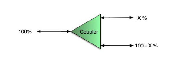
optical coupler

So for this simple 1X2 splitter, how do we test it? Simply follow the same directions for a double-ended loss test. Attach a launch reference cable to the test source of the proper wavelength (some splitters are wavelength dependent), calibrate the output of the launch cable with the meter to set the 0dB reference, attach to the source launch to the splitter, attach a receive launch cable to the output and the meter and measure loss. What you are measuring is the loss of the splitter due to the split ratio, excess loss from the manufacturing process used to make the splitter and the input and output connectors. So the loss you measure is the loss you can expect when you plug the splitter into a cable plant.

To test the loss to the second port, simply move the receive cable to the other port and read the loss from the meter. This same method works with typical PON splitters that are 1 input and 32 outputs. Set the source up on the input and use the meter and reference cable to test each output port in turn.

What about the other direction from all the output ports? (In PON terms, we call that upstream and the other way from the 1 to 32 ports direction downstream.) Simply reverse the direction of the test. If you are tesing a 1X2 splitter, there is just one other port to test, but with a 1X32, you have to move the source 32 times and record the results on the meter.
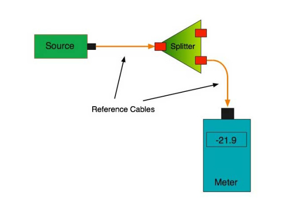
fiber-splitter

What about multiple input and outputs, for example a 2X2 coupler? You would need to test from one input port to the two outputs, then from the other input port to each of the two outputs. This involves a lot of data sometimes but it needs to be tested.

There are other tests that can be performed, including wavelength variations (test at several wavelengths), variations among outputs (compare outputs) and even crosstalk (put a signal on one output and look for signal on other outputs.)

Once installed, the splitter simply becomes one source of loss in the cable plant and is tested as part of that cable plant loss for insertion loss testing. Testing splitters with an OTDR is not the same in each direction.

Other Passive Devices

There are other passive devices that require testing, but the test methods are similar.

Fiber optic switches are devices that can switch an input to one of several outputs under electronic control. Test as you would the splitter as shown above. Switches may be designed for use in only one direction, so check the device specifications to ensure you test in the proper direction. Switches may also need testing for consistency after multiple switch cycles and crosstalk.

Attenuators are used to reduce signal levels at the receiver to prevent overloading the receiver. There is a page on using attenuators that you should read. If you need to test an attenuator alone, not part of a system, use the test for splitters above by using the attenuator to connect the launch and receive cables to see if the loss is as expected.

Wavelength-division multiplexers can be tricky to test because they require sources at a precise wavelenth and spectral width, but otherwise the test procedures are similar to other passive components.

Fiber optic couplers or splitters are available in a wide range of styles and sizes to split or combine light with minimal loss. All couplers are manufactured using a very simple proprietary process that produces reliable, low-cost devices. They are physically rugged and insensitive to operating temperatures. Couplers can be fabricated in custom fiber lengths and/or with terminations of any type.

DK Photonicswww.dkphotonics.com  specializes in designing and manufacturing of high quality optical passive components mainly for telecommunication, fiber sensor and fiber laser applications,such as PLC Splitter, WDM, FWDM, CWDM, DWDM, OADM,Optical Circulator, Isolator, PM Circulator, PM Isolator, Fused Coupler, Fused WDM, Collimator and Polarization Maintaining Components, Pump Combiner, High power isolator, Patch Cord and all kinds of connectors.

Optical Filters: Filter stacks transmit wide-angle incident light without shifting wavelength(2)

To avoid the problem of color change versus incidence angle in an optical system, thin-film-coated filter elements can be replaced by a filter consisting of a stack of different filter glasses.

JASON KECK

Wide-angle filter stack apps

There is a multitude of applications for this type of filter. In the field of digital imaging, colorimeters-which take wideband spectral energy readings-are used to profile and calibrate display devices, verifying that pixel color and intensity at the edge of a display matches the performance of pixels in the center of the display.

In astronomy, biomedical or fluorescence imaging, and mineralogy, hyperspectral imaging has many important applications. It is essential that the incident light undergo as little iridescence as possible. Also, when precision imaging instruments are expensively launched into orbit, the filters must be robust enough to withstand extreme environmental operating conditions.

In agriculture, the color of crops or food products reveals vital information. The use of Earth-observing satellites to measure the “vegetation index” of crops (a measurement of green hue) is nothing new, but the affordability of aerial drones has brought new possibilities. A drone can be programmed with GPS data to fly on a fixed pattern over a designated crop area and take wide-angle images at regular intervals, building up a picture of the vegetation index of crops. If the images used in such applications provide accurate spectral data that is as free as possible from iridescent distortion, it can give farmers precise control over fertilizer application rates and greatly improve efficiency and productivity. This is a considerable cost saving over low-resolution, narrowband satellite imagery and conventional aerial photography using manned aircraft.

Design hurdles

There are three complicating factors in the design of such filter stacks. The first is the limited choice in filter glass, limited not only by manufacturer availability but also by physics. Filter glass with an ideal edge cut-on or cut-off wavelength for an application is not always easy to find, or may be impossible to precisely manufacture. Where it is available, the designer is then limited by what the manufacturer can deliver in a reasonable time, as melts may be scheduled as infrequently as once every several years, depending on demand.

The second factor is that, while the perfect filter glass for a particular application may not exist, there are hundreds of other glass types from numerous vendors that can be combined to achieve a close approximation of the requirement.

The third complicating factor is that the design of ColorLock filters is a massively multidimensional, nonsmooth optimization challenge. Physical manufacturing requirements restrict the thickness of all combined individual layers to not exceed the overall thickness requirement of the resulting optical component, further putting restrictions on the selection of specific CWDM filter glass types.

Reynard streamlined this complex design process by developing in-house software into which all of the system requirements are fed. The software produces a manufacturable design for a filter in which the necessary materials are combined at the correct thickness in each layer. The design is then manufactured and validated for performance.

About DK Photonics

DK Photonics – www.dkphotonics.com  specializes in designing and manufacturing of high quality optical passive components such as 8CH CWDM Module,100GHz 8CH DWDM,200GHz DWDM,Mini-size CWDM,compact CWDM,Athermal AWG DWDM Module,100GHz AWG,Thermal AWG DWDM Module,1310/1490/1550nm FWDM, PLC Splitter, Optical Circulator,Optical Isolator,Fused Coupler,Mini Size Fused WDM.

Fiber Optic Connector Market Forecast-DK Photonics

According to ElectroniCast, multifiber / multichannel fiber optic connectors are set for explosive growth, led by MXC™ fiber connectors with triple-digit increases through 2018…

Aptos, CA (USA) – September 22, 2014 —ElectroniCast Consultants, a leading market & technology forecast consultancy addressing the fiber optics communications industry, today announced the release of their annual market forecast and analysis of the use offiber optic connectors and mechanical splices in communication applications.

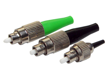
FC fiber optic connector

According to ElectroniCast, the worldwide fiber optic connector/mechanical splice consumption value reached $2.63 billion in 2013.  Multimode fiber optic connectors led the consumption value in 2013 with a 64 percent market share.  The use of multimode fiber optic connectors is forecast to increase at a rate of 14 percent per year, from $1.68 billion in 2013 to $3.24 billion in 2018.

“The multimode LC small form factor connector is forecast to maintain the leadership position in relative market share throughout the forecast period, as well as increasing at an average annual rate of 20 percent,” said Stephen Montgomery, Director of the Fiber Optic Component group at ElectroniCast.

The fastest annual growth is set to come from the use of multifiber/multichannel fiber optic connectors are set for explosive growth, led by MXC™ fiber connectors with triple-digit increases through 2018.  The newly-release connector design enables more fibers (up to 64 fibers at 25G) to be accommodated in fast-paced server/storage data center and other applications.  Both the single-mode and the multimode MXC fiber optic connectors are forecast to reach strong values by 2018.

Other new fiber optic connector designs, besides the MXC connector, are planned for deployment to address the high-density/high-speed data speeds of 25Gbps or greater in the next couple of years.

“Field-installable connectors for indoor and outdoor use are increasing in demand and thus are making a big-splash in the overall connector product lines of several competitors.  Fiber optic connector-types, such as SC, ST, LC, FC and even the MPO and other possibilities are finding their way to the marketplace.  Both mechanical-splice and fusion-splice technologies are meeting the requirements in the field-installable fiber optic product availability,” Montgomery added.

The global fiber optic connector/mechanical splice consumption is driven by a dramatic increase in bandwidth demand beyond the limits of copper.  As optical fiber use migrates closer and closer to the end user, where cable lengths are shorter with higher fiber counts, the requirements for jointing fibers becomes more critical. Splicing and connecting, play a significant role in a network’s cost and performance.

There are over 140 vendors competing for the global fiber optic connector/ mechanical splice market, which ElectroniCast tracks in a product matrix showing participation in the following: connectors, cable assemblies, optical backplanes, and fiber optic installation apparatus; however, is dominated by a few companies that have a broad base in various interconnect products.

DK Photonicswww.dkphotonics.com specializes in designing and manufacturing of high quality optical passive components mainly for telecommunication, fiber sensor and fiber laser applications,such as WDM, FWDM, CWDM, DWDM, OADM,Optical Circulator, Isolator, PM Circulator, PM Isolator, Fused Coupler, Fused WDM, Collimator, Optical Switch and Polarization Maintaining Components, Pump Combiner, High power isolator, Patch Cord and all kinds of connectors.

Market Forecast–MPO Connectors in 40/100GbE – DK Photonics

MPO fiber optic connectors used in North American 40/100GbE communication links are forecast to increase at a rate of 49.8% per year through 2018…

MPO

Aptos, CA (USA) – August 20, 2014 —ElectroniCast Consultants, a leading market & technology forecast consultancy addressing the fiber optics communications industry, today announced the release of their market forecast and analysis of the use of MPO fiber optic connectors in 40 gigabit Ethernet (GbE) and 100GbE Standard communication network links.  MPO is the industry acronym for “multi-fiber push on.”

“Applications such as video, virtualization, cloud computing, switching/routing and convergence are driving the need for bandwidth expansion in data centers, 4G/LTE (wireless) networks, and other deployments.  We continue on the path of gradually migrating from 1G to 10G to 40G and 100G and eventually beyond; and the MPO connector is a key component in 40/100GbE network links, ” said Stephen Montgomery, director of the fiber optics components group at ElectroniCast.

The use of MPO fiber optic connectors in North American 40GbE and 100GbE networks is expected to reach $28 million in 2014, an increase of 84% over last year (2013). The use of 40/100GbE MPO connectors in North American is forecast to increase at annual rate of 49.8% per year over the 2013-20189 timeframe covered in the ElectroniCast market forecast. Market forecast data in the market study refers to consumption (use) for a particular calendar year; therefore, this data is not cumulative data.

The market forecast is segment by the use of single-mode and multimode 12-fiber and 24-fiber MPO connectors, and further broken-out by the use of connectors in 40G and the connectors used in 100G.

According to the market study, the North American 40/100GbE MPO connector market expansion will be dominated by the 12-fiber multimode MPO connectors, increasing at an average annual growth rate of 48.5 percent during the forecast period.

DK Photonicswww.dkphotonics.com  specializes in designing and manufacturing of high quality optical passive components mainly for telecommunication, fiber sensor and fiber laser applications,such as PLC Splitter, WDM, FWDM, CWDM, DWDM, OADM,Optical Circulator, Isolator, PM Circulator, PM Isolator, Fused Coupler, Fused WDM, Collimator, Optical Switch and Polarization Maintaining Components, Pump Combiner, High power isolator, Patch Cord and all kinds of connectors.

Optical Isolators Global Market Forecast-DK Photonics

According to ElectroniCast, optical isolator value in Telecommunications is forecast to increase 19.6% this year…

Aptos, California (USA) – April 29, 2014  —ElectroniCast Consultants, a leading market research & technology forecast consultancy addressing the fiber optics communications industry, today announced the release of a new market forecastof the global consumption of optical isolators in optical communication and specialty applications.

According to ElectroniCast, the worldwide optical isolator consumption was led by Telecommunication applications in 2013 with a 70 percent market share or $349.7 million, and is forecasted to increase 19.6 percent in value to $418.2 million this year (2014).  Market forecast data in this study report refers to consumption (use) for a particular calendar year; therefore, this data is not cumulative data.

Optical isolators are devices that allow light to be transmitted in only one direction. They are most often used to prevent any light from reflecting back down the optical fiber, as this light would enter the source and cause backscattering and feedback problems. This is especially important for high data rate transceivers and transponders, or those devices requiring long span lengths between transceiver pairs. Optical feedback degrades signal-to-noise ratio and consequently bit-error rate.

“Continuing demand for upgrading communication networks to accommodate rapidly increasing bandwidth requirements will drive the steady consumption of optical fiber links. Optical isolators are used in with high-speed transmitters that are required to transmit longer distances and/or multiple wavelength transmitters,” stated Stephen Montgomery, Director of the Fiber Optics Components group at ElectroniCast Consultants.

Optical isolators are not widely used in Private Enterprise applications; however, worldwide use of fiber optic isolators in Cable TV controlled device deployments are forecast to grow significantly in value at an annual rate of 8.8 percent (2013-2018), as optical fiber is deployed closer to the home driven by multi-media applications.

Optical isolator units are used in a variety of Military/Aerospace applications requiring rigorous testing and harsh environment fiber optic (HEFO) certification to ensure reliability and performance.  Laser-based fiber optic technology incorporating optical isolators are used in a wide variety of air, sea, ground, and space applications.

A major user-group within the Specialty application category is Laboratory/R&D.  Optical isolators are used for noise reduction, medical imaging, pulse selection for mode locked lasers, sensing, regeneration switches, disc master, optical trapping, phase shifters, frequency modulation spectroscopy and general shuttering. The optical isolators are also used in sensing for industrial, structures and other many other communication product-oriented manufacturing/test/R&D uses.

“During the forecast period (2013-2018), bandwidth expansion demands will push for new network links, incorporating Metro Core, Metro/Access, Long Haul, Optical Fiber Amplifiers, WDM, OADM and other system-based deployments, which incorporate optical isolators,” Montgomery added.

The American region held the lead in terms of relative market share consumption value of optical isolators in 2013, with nearly 43.4 percent; however the American region is forecast to increase at a slower rate compared to the other regions (2013-2018). The Asia Pacific region (APAC) is forecast to increase in worldwide market share from 39.7 percent in 2013 to with 53.7 percent in 2018.  The Europe, Middle East, African region (EMEA) is forecast to remain in the third-place position, however, increase at a faster annual pace versus the American region.

According to ElectroniCast, the American Region leads optical isolator consumption value…

2013 – Optical Isolator Global Value Market Share (%),

By Region, $498 Million

Source: ElectroniCast Consultants

Optical Isolator Global Value Market Share (%)

DK Photonicswww.dkphotonics.com  specializes in designing and manufacturing of high quality optical passive components mainly for telecommunication, fiber sensor and fiber laser applications,such as PLC Splitter, WDM, FWDM, CWDM, DWDM, OADM,Optical Circulator, Isolator, PM Circulator, PM Isolator, Fused Coupler, Fused WDM, Collimator, Optical Switch and Polarization Maintaining Components, Pump Combiner, High power isolator, Patch Cord and all kinds of connectors.
Comparation Between EPON and GPON

With the continuous progress of science and technology, the Internet has gradually gone into the homes of the ordinary people, and the speed of broadband has increasingly become the topic of people in the entertainment and work often, from narrowband dial-up to broadband Internet, and then the fiber access Internet, broadband network, the rapid pace of PON technology gradually come to the front. Currently, there are two quite compelling PON standard has been officially released, which are GPON standard developed by the ITU / FSAN and EPON standard developed by IEEE 802.3ah working group. PON technology has been no doubt the ultimate solution for the future FTTH era. EPON and GPON who will the dominant FTTH tide has become a new hot debate. What’s the difference between EPON and GPON?

GPON and EPON Differences

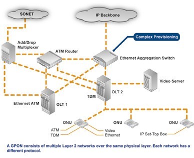
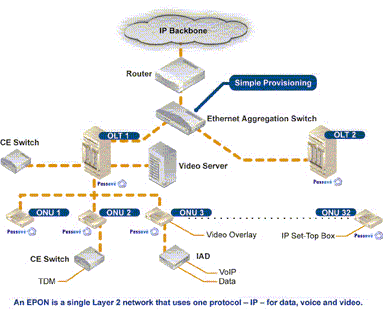
Perhaps the most dramatic distinction between the two protocols is a marked difference in architectural approach. GPON provides three Layer 2 networks: ATM for voice, Ethernet for data, and proprietary encapsulation for voice. EPON, on the other hand, employs a single Layer 2 network that uses IP to carry data, voice, and video.

A multiprotocol transport solution supports the GPON structure (Figure 1). Using ATM technology, virtual circuits are provisioned for different types of services sent from a central office location primarily to business end users. This type of transport provides high-quality service, but involves significant overhead because virtual circuits need to be provisioned for each type of service. Additionally, GPON equipment requires multiple protocol conversions, segmentation and reassembly (SAR), virtual channel (VC) termination and point-to-point protocol (PPP).

Figure 1: Diagram showing a typical GPON network.

EPON provides seamless connectivity for any type of IP-based or other “packetized” “communications” (Figure 2). Since Ethernet devices are ubiquitous from the home network all the way through to regional, national and worldwide backbone networks, implementation of EPONs can be highly cost-effective. Furthermore, based on continuing advances in the transfer rate of Ethernet-based transport — now up to 10 Gigabit Ethernet — EPON service levels for customers are scalable from T1 (1.5 Mbit/s) up through 1 Gbit/s.

Figure 2: Diagram showing a typical EPON network.

Upstream Bandwidth

Subtracting the various system run overhead from the total bandwidth of the system uplink transmission is the upstream available bandwidth. It has a great relationship with the number of the ONU contained in the system, DBA (Dynamic Bandwidth Allocation) algorithm polling cycle, the type of bearer services, as well as the various business proportion. EPON and GPON are broadband access technology, hosted business IP data services. Below we will calculate the uplink the beared pure IP services available bandwidth of EPON and GPON that contain 32 ONUs, fiber optic coupler,the case of polling period 750s.

EPON

EPON upstream rate is 1.25 Gbit/s. Because the 8B/10B line coding, each 10bit are 8bit valid data, so its effective upstream transmission bandwidth is 1 Gbit/s. EPON upstream overhead of running the system and its proportion of the total bandwidth are as following:

1. Used for the the burst reception of physical layer overhead: about 3.5%;

2. Ethernet frame encapsulation overhead: about 7.4%;

3. MPCP (Multi-Point Control Protocol) and OAM operation and management of maintenance protocol overhead: about 2.9%;

4. DBA algorithm resulting in the remaining time slots (that is not sufficient to transfer a complete Ethernet frame time slot) wasted: about 0.6%;

5. EPON upstream total overhead is all of the above about 144 Mbit/s, the available bandwidth is about 856 Mbit/s.

GPON

GPON supports a variety of rate levels, has asymmetric rate that downlink is 2.5Gbps or 1.25Gbps, the upgoing is 1.25Gbps or 622 Mbps. NRZ encoding the uplink total bandwidth for 1.244 Gbit/s, GPON upstream overhead of running the system as following:

1. The proportion of its total bandwidth is used for the the burst reception of physical layer overhead: about 2.0%;

2. GEM (GPON encapsulation method) frame and the Ethernet frame encapsulation overhead: about 5.8%;

3. The PLOAM (physical layer operation, management and maintenance) protocol overhead: about 2.1%;

4. Remaining slots of the DBA algorithm introduced the additional encapsulation overhead: about 0.8%.

5. GPON upstream total overhead is all of the above about 133 Mbit/s, the available bandwidth about 1111 Mbit/s.

40/100GbE MPO FIBER OPTIC CONNECTOR – NORTH AMERICA MARKET FORECAST

According to ElectroniCast, 12-fiber single mode MPO connector consumption value will increase 141% per year through 2016…

ElectroniCast Consultants, a leading market research & technology forecast consultancy addressing the fiber optics communications industry, today announced the release of their annual market forecast of the North American consumption of MPO Fiber Optic Connectors used in 40 and 100GbE communication links.

In 2006, the IEEE 802.3 working group formed the Higher Speed Study Group (HSSG) and found that the growth in bandwidth for network aggregation applications was outpacing the capabilities of networks employing link aggregation with 10 Gigabit Ethernet. (The standard was announced in July 2007 and was ratified on June 17, 2010).

Applications such as video, virtualization (cloud computing), switching/routing and convergence are driving the need for bandwidth expansion. We continue on the path of gradually developing of growth (and change) from 1G to 10G to 40G and 100G. For data center (DC) environments operating at 40GbE or 100GbE, fiber optic cabling is generally recommended because its reach supports a wider range of deployment configurations compared to copper solutions.

The capability to choose increased speed will enable networks to play with the 10GbE resources to the access layer allowing 40/100GbE to handle traffic at the aggregation and core layers.  In this market research report, ElectroniCast Consultants provides their 2011-2016 forecast and analysis of MPO fiber optic connectors used in North American 40/100GbE optical communication networks.

The 10GbE movement into the data centers will continue; however, “future-proofing” is continuing with an accent (40/100G), which is driven by significant broadband expansion demands, especially in regards to network productivity and operating expenses (OPEX costs).

According to ElectroniCast, 12-fiber multimode MPO patchcord dominate the North American (Mexico, Canada and the United States) 40/100GbE MPO connector marketplace in 2012; however, 12-fiber single mode MPO connector consumption value will increase at the fastest pace of 141% per year through 2016.

According to ElectroniCast, 12-fiber multimode MPO connectors currently dominate the North American 40/100GbE MPO connector marketplace, based on consumption value… 

40 and 100 GbE MPO Connector Value

North America Market Share (%) in 2012, by Type

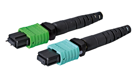
                      mpo patchcord                          
(Source: ElectroniCast Consultants)

DK Photonicswww.dkphotonics.com  specializes in designing and manufacturing of high quality optical passive components mainly for telecommunication, fiber sensor and fiber laser applications,such as PLC Splitter, WDM, FWDM, CWDM, DWDM, OADM, Circulator, Isolator, PM Circulator, PM Isolator, Fused Coupler, Fused WDM, Collimator, Optical Switch and Polarization Maintaining Components, Pump Combiner, High power isolator, Patch Cord and all kinds of connectors.
Planar Lightwave Circuit (PLC) Splitters Market Forecast

Telecommunication applications dominate the worldwide PLC splitter marketplace…

ElectroniCast Consultants, a leading market/technology consultancy, today announced the report release of their market forecast of the global consumption of Planar Lightwave Circuit (PLC) splitters used in Fiber Optic Communication Networks.

This ElectroniCast study report details of last year’s consumption and forecasts to the year 2017 of PLC splitters by product-level (level of fabrication), in selected optical communication applications.   There are actually three (3) separate market forecasts:

According to ElectroniCast, the PON, FTTx, and Telecommunication network applications dominate the worldwide PLC splitter compact device consumption value in 2012 with 77% in relative market share; followed by the cable TV segment, the PLC splitters used in Test/Measurement applications and then Harsh Environment (Military/Aerospace, Industrial) and finally Private Enterprise Networks.

In the report, ElectroniCast provides their market data covering the following optical communication applications:

  • Passive Optical Network (PON) / FTTX / Telecommunication Networks
  • Cable TV (CATV)
  • Fiber Optic Test/Measurement
  • Private Enterprise/Data Centers/Local Area Networks (LANs)
  • Harsh Environment (Military, Industrial, Other)

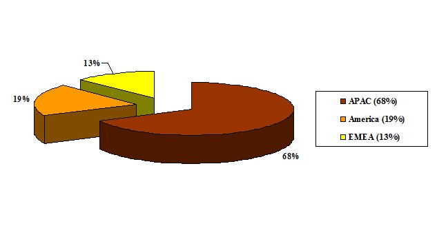
In 2012, the Asia Pacific region (APAC) region leads in the consumption of PLC splitter compact devices with 68% of the worldwide value, followed by the American region and finally the EMEA region.

According to ElectroniCast, the Asia Pacific region dominates the worldwide value of PLC splitters with 68% in 2012…

PLC Splitter Component-Level Compact Devices

2012 – Global Consumption Value Market Share (%), by Region

 (Source: ElectroniCast Consultants)

 PLC

DK Photonicswww.dkphotonics.com  specializes in designing and manufacturing of high quality optical passive components mainly for telecommunication, fiber sensor and fiber laser applications,such as PLC Splitter, WDM, FWDM, CWDM, DWDM, OADM,Optical Circulator, Isolator, PM Circulator, PM Isolator, Fused Coupler, Fused WDM, Collimator, Optical Switch and Polarization Maintaining Components, Pump Combiner, High power isolator, Patch Cord and all kinds of connectors.