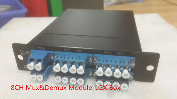
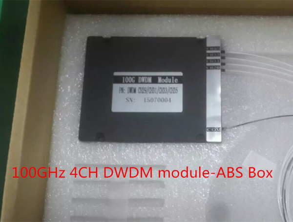
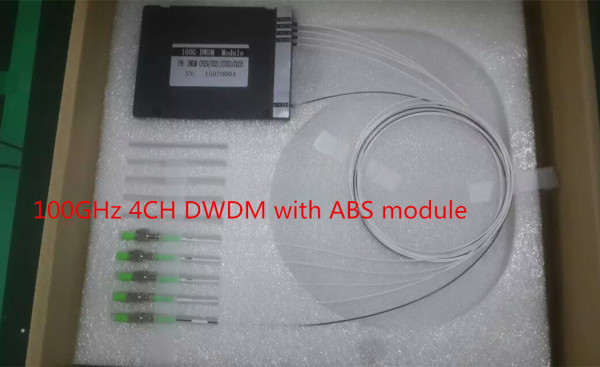
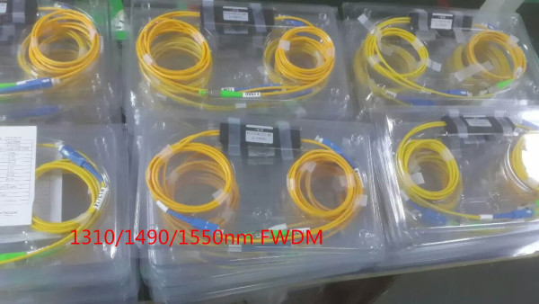
Combining the Multiplexer and Demultiplexer into One

As advancements in technology take place, the need for faster data transmission emerges. Often, continuing with the old equipment results in major losses. If you have been fed up of the existing data transfer speeds at your place, it is certainly the time when you should look out for change. And not just change, a solution which is cost effective, of the best quality and the best service should always be your goal.

D K Photonics Technology Limited is one of the leading companies in designing and manufacturing of high quality optical passive components, which includes a large array of fiber-optic components. You can count on them to get the best solution for your everyday problems. They have brought the advantages of both the multiplexer, which is multi input and single output device and the demultiplexer, which is a single input and multiple output device, into one product. It has eradicated the need for having both the products separately.

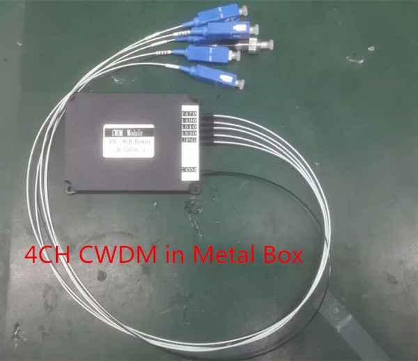
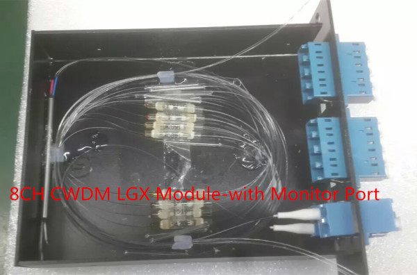
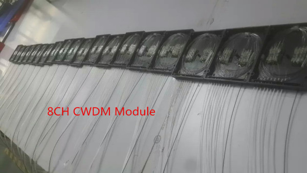
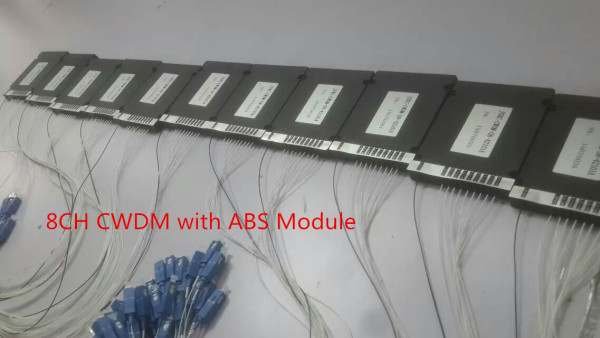
About our CWDM Mux and DeMux Module:

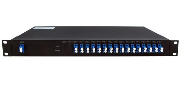
For industries employing multiplexer and demultiplexer for telecommunication, fiber sensor and fiber laser applications such as line monitoring, networking, cellular communications, optical amplifiers etc. DK Photonics CWDM MUX+DEMUX Module is an ideal choice. It supports wavelengths between 1270nm to 1610nm in 20nm increments, allowing different services up to 10Gbps to be transported across the same fiber link. It is the latest product that offers a competitive advantage to the industry using it.

The features of CWDM Mux+DeMux Module are:

  • Low insertion loss
  • Wide pass band
  • High channel isolation
  • High stability and reliability
  • Epoxy free on optical path

With so many advanced features, it surely is going to beat the obsolete products. The module combines the need for a multiplexer and demultiplexer into one product. Besides, minimizing the number of wires that are required for the multiple transmissions, the information is multiplexed over a single high data rate link, and then demultiplexed at the other end, along a single communication channel. That is what makes it a more sought after choice.

If you intend to increase your data transfer needs with the optical Mux+DeMux module, you are just a few a steps away. Get a Mux+DeMux module for your industry and connect the data line is to the output line. Enjoy the difference!

Our contact and support:

We are always reachable at the following destinations:

  • Website: http://www.dkphotonics.com
  • E-mail: info@dkphotonics.com
  • Tel:+86-755-36820366
  • Fax:+86-755-26746512
  • Add: DK Photonics Technology Limited

7/F, Bldg. C, Qinghu Technology Park

Qingxiang Rd., Longhua New Dis.

Shenzhen, Guangdong, China  518109


Profitability of the Optical Component Business Improved Last Year and It May Set a New Record in 2016

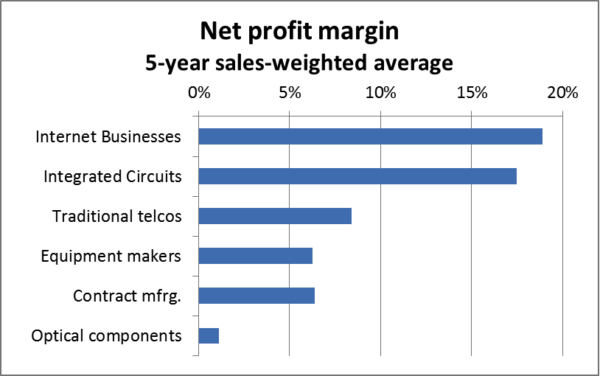
The average profitability of optical passive component and module suppliers was very close to zero over the last 5 years, despite strong demand for optics. Compared to every other level of the industry supply chain, profitability of the optical component manufacturers was the lowest by far.

Financial reports of several suppliers of optics started to show signs of improvement over the last 2-3 quarters. The average profitability of optical component and module vendors was 2% in 2015, compared to a loss of 1% in 2014. There is a good chance for reaching 5-7% profitability in 2016-2017 and setting a new record. The highest profitability achieved so far was 5.5% in 2010, preceded by more than ten years of heavy losses.

Net profit margins in the optical components value chain

May 25, 2016 News_Release_Profitability of the Optical Component Business Improved Last Year and It May Set a New Record in 2016

Source: Public financial reports

Several component vendors restructured their businesses in 2013-2014 and these efforts are starting to pay off now. Accelink, Applied Optoelectronics, Coadna, Neophotonics and Oclaro reported significant improvements in financial performance. Acacia joined the list of publicly traded vendors recently and holds the record with a 17% net margin for 2015. Finisar’s profits started to improve in the second half of 2015 and we expect this trend to continue.

However, the average profitability is likely to stay in the single digits for a while. This industry is very competitive and it is likely to remain so for the next several years. Demanding customers, shorter product lifecycles and investments required to support development of new products are a heavy burden for suppliers. There are close to 40 vendors in the race to offer 100GbE optics to the cloud companies building mega-datacenters. Not many of these vendors will be successful in the long term, but they will continue to put pressure on the profitability of larger publicly traded companies in the industry.

Many start-up companies, betting their future on supplying high-speed optics to cloud vendors, develop products based on silicon photonics and expect that this new technology will give them a sustainable cost advantage. LightCounting’s report on Integrated Optical Devices offers detailed analysis of the opportunities for silicon photonics technology, and recognizes the potential advantages of this technology. However, we expect that a majority of high-speed Ethernet optics used in mega-datacenters will still be based on more established InP and GaAs based optics even in 2021.

Despite all the risks, developing new manufacturing technologies offers a path to sustainable competitive advantage and long-term profitability. Silicon photonics holds a promise for being such a technology. High-valued acquisitions of silicon photonics companies and the recent IPO of Acacia offered much needed success stories for investors. However, the risk remains high. Many other vendors, starting just to ship silicon photonics based products now, will have to prove themselves in 2016-2018.

DK Photonics – www.dkphotonics.com  specializes in designing and manufacturing of high quality optical passive components mainly for telecommunication, fiber sensor and fiber laser applications,such as 1064nm High Power Isolator,1064nm Components, PM Components, (2+1)x1 Pump Combiner,Pump Laser Protector,Mini-size CWDM,100GHz DWDM,Optical Circulator,PM Circulator,PM Isolator,Fused Coupler,Mini Size Fused WDM.

Field-Terminated Fusion Splice-On Connector-North American Market Forecast

According to ElectroniCast, the quantity of field-terminated fiber optic splice-on connectors in North America will increase at an explosive annual rate of 41.9% …

ElectroniCast Consultants, a leading market research & technology forecast consultancy addressing the fiber optics communications industry, today announced the release of a new market forecast of the consumption of field terminated fiber optic fusion splice-on connectors in North America.

Fusion_Splice_on_Connector

Field terminated fiber optic fusion Splice On Connectors (SOC) are installed for rapid repairs or for limited space situations where pre-terminated fiber cabling may be difficult, such as when the cable assembly needs to pass through small openings such as conduit.  The splice-on connectors are an option when the precise length of the optical fiber link is not pre-determined and a field-installed termination solution is required, such as in Fiber to the Home (FTTH) and other communication applications.

Last year, 306-thousand field-terminated fiber optic fusion splice-on connectors were installed in non-OEM applications in North America.  The number of connectors is forecast to increase at an explosive rate of 41.9% per year, reaching 2.49 million units in 2020.  Market forecast data in this study report refers to consumption (use) for a particular calendar year; therefore, this data is not cumulative data.

The Telecommunications application category is forecast to maintain the leadership in relative market share through the year 2018, until the Premises Networks application category is set to capture the lead.  Telecommunication use is forecast for 35.5% annual growth in quantity (2014-2020), mainly driven by access optical fiber deployment.  The Cable TV application is also driven by the use of connectors for FTTH (Home) and FTTB (Building/MDUs – Multiple Dwelling Units).

The market forecast segments the connectors by single-mode and multimode optical fiber, as well as into the following types: MPO, LC, FC, ST, SC, and other.  The use of single mode fiber optic field-terminated fusion splice-on connectors in North America is forecast to increase from 173.8-thousand units in 2014 to 1.49 million in 2020.  Multimode fiber is best suited for use in short lengths, such as those used in datacom and specialty networks and in 2020, multimode connectors are expected to reach 1-million units.

“In 2014 in North America, 4.3-thousand new fusion splicers were brought into Premises Datacom, and the use of field terminated fusion splice on connectors is a major market driver for the use of fiber optic fusion splicers used in premises network applications, the data center (DC) and longer link length datacom cable installations,” said Stephen Montgomery, Director of the ElectroniCast market study.

“The SOCs are emerging as a viable alternative to pre-terminated fiber optic cables (pigtail and cable assemblies/ patch cords).  Also, based on primary research interviews with network planners and installers, we are finding that field terminated fusion splice-on connectors are rapidly being accepted as a go-to solution.  With SOCs, communication network technicians can install reliable cable links with exact lengths, eliminating cable shortness or excess slack that is typically a result with the pre-terminated cable solution,” Montgomery added.

Tags: CWDM Multiplexer, DWDM Multiplexer,19″ rack mount chassis CWDM, ABS plastic box, CWDM MUX/DEMUX Module,  LGX CWDM Module,8CH CWDM Module, 16CH CWDM Module

The Modern Data Center – Modular Data Center

The modern data center is a complex place. The proliferation of mobile devices, like tablets and smartphones, place an ever-increasing pressure on the IT departments and data centers. End-user and customers’ expectation levels have never been higher and the demand for data shows no sign of slowing down. Data center managers must manage all of these elements while also remaining efficient and keeping costs under control. So where does the data center go from here?Modular Data Center

One thing I have noticed in the evolution of the modern data center is that the facilities are gaining importance; improving energy efficiency and IT management have come to the forefront. Maximizing the organization’s resources is vital, and that means delivering more to facilities and equipment without expending more on staffing. IDC forecasts that during the next two years, 25 percent of all large and mid-sized businesses will address the power and cooling facility mismatches in their data centers with new IT systems and put a 75 percent cap on data center space used. So there again is the crucial challenge of doing more and innovating while keeping budgets and spend under control.

Another key part of the next generation data center mix is automation. Today’s data center manager is engaged in sourcing the right automation tools that will help them manage energy consumption and add new technology without disrupting normal operations. These are a few of the key challenges in the modern data center—so data center managers and IT departments must find ways to address them.

Where does the Data Center Go Next?

At the heart of data center evolution is the information technology sector’s rapid rate of change. Many new products and services must be implemented with much less time to value, and data centers need to be agile enough to assess and accommodate them all. If you examine enterprise data centers, then you might observe the ways that cloud computing and hyperscale innovations are displacing traditional enterprise systems, with new paradigms pioneered by innovators like Amazon and Google. With new options being developed, enterprises now have to chart strategies for cloud computing, including public, private or hybrid cloud. Gauging where the technology will go next is difficult to tell. Will the traditional vendors, such as Cisco and EMC, prevail or will new paradigms from Nutanix or Simplivity disrupt and displace these traditional data center dominators?

The race is on to manage the rapid rate of change while also staying agile, meeting end-user expectations and managing costs. For example, data center managers must handle the level of capacity their data center requires while ensuring they don’t overspend on unused capacity. This is where the focus on data center design comes into play.

Taking the Data Center Forward

These specific needs and challenges that the modern data center faces require working with the right tools and solutions. Modular, purpose-built data center infrastructure allows organizations to develop data center services based on need—when capacity rises and where capacity is needed. For example, we’ve observed in Singapore that most data centers operate slightly above 2.1 Power Usage Effectiveness (PUE). This means that companies spend more on cooling their data center rather than on operating and powering the IT equipment. It is a simple challenge—drive efficiency without impacting operations. You want to drive PUE down to approximately 1.06, regardless of where you need to operate, and reap huge energy savings while better serving customers. If done right, there is a positive environmental impact.

Changing the paradigm of the traditional data center enables organizations to reap these rewards. Assessing and establishing business objectives that reflect what is possible, rather than what always has been or what is easier and more comfortable, has led to innovative services and new business models that reset the competitive standards for everyone. Better PUE is a mandatory step in this process. The PUE journey continues as evidenced by Amazon, which had recently taken to harnessing wind to power its data centers. Modular data centers will play a major part in this PUE journey, thanks to more efficient use of energy and greater flexible support for resiliency and compute density.

Testing Fiber Optic Splitters Or Other Passive Devices

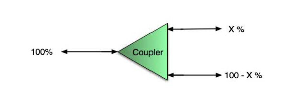
A fiber optic splitter is a device that splits the fiber optic light into several parts by a certain ratio. For example, when a beam of fiber optic light transmitted from a 1X4 equal ratio splitter, it will be divided into 4-fiber optic light by equal ratio that is each beam is 1/4 or 25% of the original source one. A Optical Splitter is different from WDM. WDM can divide the different wavelength fiber optic light into different channels. fiber optic splitter divide the light power and send it to different channels.

Most Splitters available in 900µm loose tube and 250µm bare fiber. 1×2 and 2×2 couplers come standard with a protective metal sleeve to cover the split. Higher output counts are built with a box to protect the splitting components.

Testing a coupler or splitter (both names are used for the same device) or other passive fiber optic devices like switches is little different from testing a patchcord or cable plant using the two industry standard tests, OFSTP-14 for double-ended loss (connectors on both ends) or FOTP-171 for single-ended testing.

First we should define what these passive devices are. An optical coupler is a passive device that can split or combine signals in optical fibers. They are named by the number of inputs and outputs, so a splitter with one input and 2 outputs is a 1×2 fiber splitter, and a PON splitter with one input and 32 outputs is 1×32 splitter. Some PON splitters have two inputs so it would be a 2X32. Here is a table of typical losses for splitters.

Splitter-Ratio

Important Note! Mode Conditioning can be very important to testing couplers. Some of the ways they are manufactured make them very sensitive to mode conditioning, especially multimode but even singlemode couplers. Singlemode couplers should always be tested with a small loop in the launch cable (tied down so it does not change and set the 0dB reference with the loop.) Multimode couplers should be mode conditioned by a mandrel wrap or similar to ensure consistency.

Let’s start with the simplest type. Shown below is a simple 1X2 splitter with one input and two outputs. Basically, in one direction it splits the signal into 2 parts to couple to two fibers. If the split is equal, each fiber will carry a signal that is 3dB less than the input (3dB being a factor of two) plus some excess loss in the coupler and perhaps the connectors on the splitter module. Going the other direction, signals in either fiber will be combined into the one fiber on the other side. The loss is this direction is a function of how the coupler is made. Some couplers are made by twisting two fibers together and fusing them in high heat, so the coupler is really a 2X2 coupler in which case the loss is the same (3dB plus excess loss) in either direction. Some splitters use optical integrated components, so they can be true splitters and the loss in each direction may different.
optical coupler

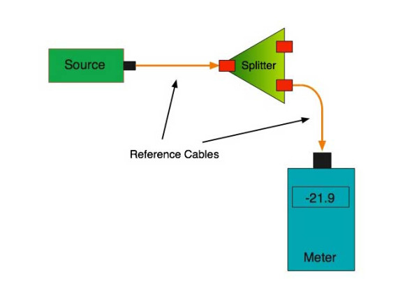
So for this simple 1X2 splitter, how do we test it? Simply follow the same directions for a double-ended loss test. Attach a launch reference cable to the test source of the proper wavelength (some splitters are wavelength dependent), calibrate the output of the launch cable with the meter to set the 0dB reference, attach to the source launch to the splitter, attach a receive launch cable to the output and the meter and measure loss. What you are measuring is the loss of the splitter due to the split ratio, excess loss from the manufacturing process used to make the splitter and the input and output connectors. So the loss you measure is the loss you can expect when you plug the splitter into a cable plant.

To test the loss to the second port, simply move the receive cable to the other port and read the loss from the meter. This same method works with typical PON splitters that are 1 input and 32 outputs. Set the source up on the input and use the meter and reference cable to test each output port in turn.

What about the other direction from all the output ports? (In PON terms, we call that upstream and the other way from the 1 to 32 ports direction downstream.) Simply reverse the direction of the test. If you are tesing a 1X2 splitter, there is just one other port to test, but with a 1X32, you have to move the source 32 times and record the results on the meter.
fiber-splitter

What about multiple input and outputs, for example a 2X2 coupler? You would need to test from one input port to the two outputs, then from the other input port to each of the two outputs. This involves a lot of data sometimes but it needs to be tested.

There are other tests that can be performed, including wavelength variations (test at several wavelengths), variations among outputs (compare outputs) and even crosstalk (put a signal on one output and look for signal on other outputs.)

Once installed, the splitter simply becomes one source of loss in the cable plant and is tested as part of that cable plant loss for insertion loss testing. Testing splitters with an OTDR is not the same in each direction.

Other Passive Devices

There are other passive devices that require testing, but the test methods are similar.

Fiber optic switches are devices that can switch an input to one of several outputs under electronic control. Test as you would the splitter as shown above. Switches may be designed for use in only one direction, so check the device specifications to ensure you test in the proper direction. Switches may also need testing for consistency after multiple switch cycles and crosstalk.

Attenuators are used to reduce signal levels at the receiver to prevent overloading the receiver. There is a page on using attenuators that you should read. If you need to test an attenuator alone, not part of a system, use the test for splitters above by using the attenuator to connect the launch and receive cables to see if the loss is as expected.

Wavelength-division multiplexers can be tricky to test because they require sources at a precise wavelenth and spectral width, but otherwise the test procedures are similar to other passive components.

Fiber optic couplers or splitters are available in a wide range of styles and sizes to split or combine light with minimal loss. All couplers are manufactured using a very simple proprietary process that produces reliable, low-cost devices. They are physically rugged and insensitive to operating temperatures. Couplers can be fabricated in custom fiber lengths and/or with terminations of any type.

DK Photonicswww.dkphotonics.com  specializes in designing and manufacturing of high quality optical passive components mainly for telecommunication, fiber sensor and fiber laser applications,such as PLC Splitter, WDM, FWDM, CWDM, DWDM, OADM,Optical Circulator, Isolator, PM Circulator, PM Isolator, Fused Coupler, Fused WDM, Collimator and Polarization Maintaining Components, Pump Combiner, High power isolator, Patch Cord and all kinds of connectors.
Optical Filters: Filter stacks transmit wide-angle incident light without shifting wavelength(1)

To avoid the problem of color change versus incidence angle in an optical system, thin-film-coated filter elements can be replaced by a filter consisting of a stack of different filter glasses.

JASON KECK

Wide-angle imaging systems have to overcome numerous problems. Distortion of the shape of objects in the scene is the predominant issue, recognizable as the “fish-eye lens” look that is often corrected in software. However, lens distortion is not the only problem.

Iridescence, or the change in transmitted or reflected color of light viewed from different angles, is a phenomenon that can be found both in nature and in artificial light-detecting systems with precise color requirements, where it can cause many problems.

Wide-angle color-sensing applications commonly require that a CWDM wavelength must be detectable regardless of the incident angle. Iridescence through a thin-film-coated optical element can cause problems in this situation by distorting the spectral transmission of light coming from peripheral objects.

Maximizing light transmission in a thin-film WDM coating’s passband while blocking out-of-band light is a requirement for coated optical components such as dielectric filters; however, the wavelength’s transition commonly only remains steady within relatively narrow cone angles. Beyond angles of 5°, such filters are susceptible to iridescence, observable as a change of color, or “blueshift.” As the angle of light entering the filter increases, the light propagates through more of each thin-film stack layer, altering the apparent overall thickness of the optical-filter stack and affecting the performance of the original intended design. This can make such filters unsuitable for wide-angle imaging applications with bright illumination and where higher standards of consistency are required of the wavelength of all incident light.

One of the more convoluted wide-angle imaging solutions is the use of a cluster of cameras or a polycamera, pointing in various directions like the compound eye of an insect; the resulting multiple pictures are then assembled into one image in software. Although the light entering each camera thus fills only a narrow cone angle, the complexity and resultant high expense of such a system is obvious.

Engineers at Reynard have addressed this problem in a single optical device with a system in which two or more layers of filter glass are combined into a stacked configuration. These ColorLock filter stacks eliminate the wavelength shift as incident angle increases and are customized to meet specific system needs.

Software is used to determine the exact composition and thickness of the layers in these filters; the software determines a merit function that best estimates the filter requirements and allows filter stacks to be designed for band pass, short-wave pass, long-wave pass, or user-specified functions. Incident angles can be as high as 50° without any shift in the transmitted wavelength, while more traditional coated filters with the same conditions would see a significant shift toward shorter wavelengths.


About DK Photonics

DK Photonics – www.dkphotonics.com  specializes in designing and manufacturing of high quality optical passive components such as 8CH CWDM Module,100GHz 8CH DWDM,200GHz DWDM,Mini-size CWDM,compact CWDM,Athermal AWG DWDM Module,100GHz AWG,Thermal AWG DWDM Module,1310/1490/1550nm FWDM, PLC Splitter, Optical Circulator,Optical Isolator,Fused Coupler,Mini Size Fused WDM.

Differences Between FBT Coupler and PLC splitters

Optical networks require signal being splitted somewhere in design to serve for multiple customers. Splitter technology has made a huge step forward in the past few years by introducing PLC (Planar Lightwave Circuit) splitter. It has proven itself as a higher reliable type of device compared to the traditional FBT (Fused Biconical Taper) splitter. While being similar in size and outer appearance, both types of splitters provide data and video access for business and private customers. However, internally the technologies behind these types vary, thus giving  service providers a possibility to choose a more appropriate solution.

FBT splitter is made out of materials that are easily available, for example steel, fiber, hot dorm and others. All of these materials are low-price, which determines the low cost of the device itself. The technology of the device manufacturing is relatively simple, which has the impact on its price as well. In scenario where multiple splits are needed, the size of the device may become an issue. It is important to keep in mind that splitters are being deployed in the fields either in cabinets or in strand mountings, so the size of device plays a critical role. FBT splitters only support three wavelengths (850/1310/1550 nm) which makes these devices unable to operate on other wavelengths. Inability of adjusting wavelengths makes FBT splitters less customizable for different purposes. Moreover, the devices are to a high extent temperature sensitive, providing a stable working range of -5 to 75 C. In certain areas, such as Scandinavian countries this temperature restrictions may be crucial. The signal processed by FBT splitters cannot be splitted evenly due to lack of management of the signals

PLC splitter manufacturing technology is more complex. It uses semiconductor technology (lithography, etching, developer technology) production, hence it is more difficult to manufacture. Therefore, the price of the device is higher. However, there is a number of advantages the device possesses. The size of the device is compact, compared to FBT splitters, making it suitable for density applications. PLC splitter operates at wider temperature range (-40 to 85 C), allowing its deploying in the areas of extreme climate. The split ratio goes up to 64, providing a high reliability. Furthermore, the signal can be split equally due to technology implemented. A range of wavelengths (1260 – 1650 nm) is provided, so the wavelengths are adjustable. Critical points of the device that might fail are input and output, so the general risk of failure is low.

Differences Between FBT and PLC splitters

 Table 1. FBT and PLC splitter feature comparison

DK Photonicswww.dkphotonics.com  specializes in designing and manufacturing of high quality optical passive components mainly for telecommunication, fiber sensor and fiber laser applications,such as PLC Splitter, WDM, FWDM, CWDM, DWDM, OADM,Optical Circulator, Isolator, PM Circulator, PM Isolator, Fused Coupler, Fused WDM, Collimator, Optical Switch and Polarization Maintaining Components, Pump Combiner, High power isolator, Patch Cord and all kinds of connectors.
Ovum: Optical components market to grow 8% in 2014 from $6.8 bn in 2013

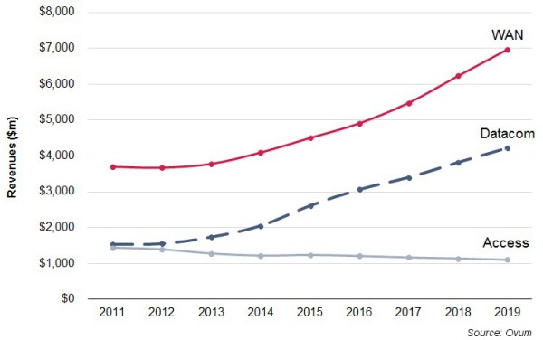
The global optical components (OC) market is expected to grow 8 percent in 2014 from $6.8 billion in 2013, said Ovum.

In 2013, the OC market increased 3 percent from 2012. Ovum said main growth drivers in 2013 were data communication sales driven by large data centers, 100G coherent demand, and unexpected growth in sales of transceivers for fiber-to-the-antenna applications for 4G build-outs.

“Demand for 100G metro–optimized transmission gear will begin shipments and ramp in 2015. Multiple component vendors introduced components and pluggable optics for 100GHz DWDM in anticipation. Opportunities are also emerging in the data center for high-speed interconnects,” said Daryl Inniss, practice leader for Telecoms Components at Ovum.

In the first quarter of 2014, the optical components market declined 1 percent sequentially and grew 7 percent compared to the year-ago period.  New lower telecom prices were one of the main reasons for the marginal growth in OC on quarter-on-quarter basis.

Ovm said demand for 100G components for coherent transmission in WAN, datacom transceivers at 10 and 40G, and fiber-to-the-antenna transceivers is expected to continue. Traffic continues to increase, and high-speed optics being used in new applications are helping to drive the market forward.

Global-optical-components-market-forecast

The WAN OC segment, which includes components in telecom carriers’ core and metro networks, the largest segment, will grow at a compound annual growth rate (CAGR) of 11 percent to $7 billion in 2019. Demand for 100G components and modules is a big driver for growth in WAN.  Ovum expects strong demand for pluggable coherent transceivers in 2015.

Datacom will be expanding at a 16 percent CAGR to reach $4.2 billion in 2019 — led by demand for 10 and 40G components in the early years and then 100G in the later years driven by the availability of server ports supporting data rates greater than 10G.

Access — including CATV, FTTx and transceivers for the fiber-to-the-antenna application — will decline at 2 percent CAGR to $1.1 billion in 2019. The decline will be driven by the FTTx application, where volumes are nearly constant through the forecast period but price declines are projected to pull down revenues.


DK Photonicswww.dkphotonics.com  specializes in designing and manufacturing of high quality optical passive components mainly for telecommunication, fiber sensor and fiber laser applications,such as PLC Splitter, WDM, FWDM, CWDM, DWDM, OADM,Optical Circulator, Isolator, PM Circulator, PM Isolator, Fused Coupler, Fused WDM, Collimator, Optical Switch and Polarization Maintaining Components, Pump Combiner, High power isolator, Patch Cord and all kinds of connectors.
Huawei, Rostelecom collaborate on FTTH distribution boxes—DK Photonics

Huawei says it has collaborated with Russian service provider Rostelecom to develop floor distribution boxes (FDBs) for use in Rostelecom’s flexible fiber to the home (FTTH) deployments. The FDBs will help improve the efficiency of the operator’s FTTH deployments, particularly in sparsely populated areas, Huawei says.

Rostelecom is under a mandate from the Russian government to connect 13 million CWDM Module users by 2015, Huawei says. This task is complicated by the fact that much of the operator’s footprint covers rural areas.

To improve deployment efficiency, Huawei says it recommended what it calls “the thin-covered network deployment model.” According to the model, fiber-optic networks are constructed to user access points and the FDBs, the latter of which are used as the interface between the outside plant and the inside plant. As the network expands and more users are connected, pre-made drop cables can be used for plug-and-play, quick service provisioning.

The customized FDBs were designed for success-based deployment. Rostelecom can deploy FDBs that provide access to a single user, then add connections as many as four or eight users as take rates improve. Technicians can complete the expansion in one minute without the use of tools, Huawei says.

Huawei and Rostelecom will further collaborate on other network elements, including the closure, optical splitter, and fiber distribution terminal (FDT), the technology provider added.

For more information on FTTx products, visit the DK Photonics Website.

DK Photonicswww.dkphotonics.com  specializes in designing and manufacturing of high quality optical passive components mainly for telecommunication, fiber sensor and fiber laser applications,such as PLC Splitter, WDM, FWDM, CWDM, DWDM, OADM,Optical Circulator, Isolator, PM Circulator, PM Isolator, Fused Coupler, Fused WDM, Collimator, Optical Switch and Polarization Maintaining Components, Pump Combiner, High power isolator, Patch Cord and all kinds of connectors.