How effective is Polarization Maintaining (PM) Isolator?

Polarization Maintaining Isolator is also known as Fiber Optic Isolator which allows light to travel only in one direction. For any state of polarization, it minimizes the back reflection and back scattering in the reverse direction. It is a two port micro-optic device built with PM panda fiber. Polarization Maintaining Isolator is used widely in amplifier systems, fiber optic systems, and lasers. It prevents unwanted feedback into an optical oscillator and the device operations are dependent on the Faraday’s effect turn.
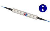
Polarization Maintaining Isolator

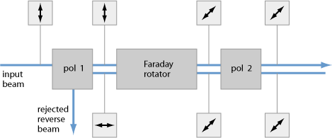
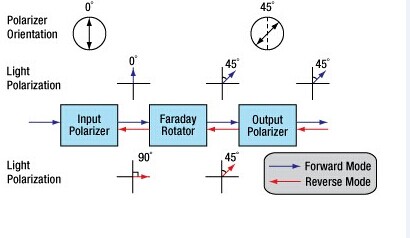
Faraday rotator is the main component of the optical isolator. The polarization dependent isolator mainly consists of 3 parts like an input polarizer, a Faraday rotator, and an output polarizer. The output polarizer is known as the analyser. Input polarizer vertically polarizes the light traveling in the forward direction. Using the analyser, the light traveling in the backward direction becomes polarized by 45°. The polarization dependent isolators are mainly used in free space optical systems as the polarization of source is maintained well by the system.

What are the devices in which the isolator is used?

PM isolator is used in communication systems, polarization maintaining fiber-optic amplifier and instrumentation applications. Also, the insulating system is used in CATV Fiberoptic Links, Fiberoptic System Testing and Fiberoptic LAN System.
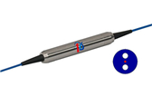
Here are the best features of polarization maintaining optical isolator –

  • High Extinction Ratio
  • High Return Loss
  • High Isolator
  • Epoxy Free Optical Ratio
  • Low Insertion Loss

The light traveling in the forward direction is split by the input birefringent wedge into a vertical component which is called ordinary ray and a horizontal component is known as extraordinary ray. The rotator rotates both the o-ray and e-ray by 45°. Again the output birefringent wedge combines the two components. On either sides of the isolator, collimators are used and the beam is split & diverged in the isolated direction.
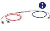
There are now companies who specialize in the manufacturing of the isolators for various applications. Based on the requirement of applications, isolators are manufactured precisely. Also, one can get the isolators online and the common PM Isolators available online are Polarization Maintaining Isolator 1310 & 1480 & 1550nm and Polarization Maintaining Tap Isolator 1310 & 1550nm.

Work Theory of the Laser Cutting Machine(2)

Cutting methods of laser cutting machine

Vaporization cutting

It means that vaporization is the main way to remove the processed material. In the process of vaporization cutting, workpiece surface is heated to vaporization temperature quickly by focused laser beams, forming High pressure steam and spraying outward at supersonic speeds. In the meantime, a hole is formed in the laser active area and laser beams reflex several times in the hole to increase the absorption of laser pump power combiner by material.

When high-pressure vapors spray outward, the melted materials are blown away in the kerf till the workpiece is finally cut. Vaporization cutting needs very high power density, which is eighth power of ten watt above per square centimeter. It is usually applied in low flash point materials and refractory materials.

Reaction Fusion Cutting

Reaction Fusion Cutting

When assistant airflow not only blows the melted materials from the kerf but also has thermal reaction with the workpiece, this is the so-called reaction fusion cutting. Gases that can have reaction with workpiece are oxygen or mixture gases containing oxygen. When the surface  temperature of workpiece reach to ignition temperature, strong combustion heat release occurs to improve the laser cutting ability.

Combustion heat release of low carbon steel and stainless steel is 60%. And it is about 90% for reactive metals like titanium.

Compared to vaporization cutting and general fusion cutting, reaction fusion cutting need less laser power density. However, reaction fusion cutting may effect the performance of worpiece since the combustion reaction can lead to chemical reaction on materials.

Fusion Cutting

When adding a assistant airflow system coaxial with laser to  blow the melted materials away from kerf, this kind of cutting is fusion cutting. In fusion fiber coupler cutting, workpiece needn’t to be heated to vaporization temperature so the required laser power density is reduced greatly.

Laser Scribing

It is mainly used in semiconductor materials, in which laser of high power density make a shallow groove in the semiconductor materials of the workpiece and then makes it crack through mechanistic or vibratory methods. The quality is valued by the surface fragments and size of heat affect area.

Cold Chipping

It is a new processing method, which is put forward along with ultraviolet band superpower excimer laser appeared in recent years. The basic theory is that energy of ultraviolet photons is similar to binding energy of many organic materials; this high-energy photons are used to impact bond organic materials thus make it crack, achieving purpose of cutting. This new technology has promising application future, especially in electron industry.

Thermal Stress Cutting

Mechanism of thermal stress cutting is that laser beams heat an area of fragile material to produce evident temperature gradient. The high surface temperature makes expansion and inner lower temperature hinders expansion, forming pulling stress in the surface and radial crushing stress inside. When the two stresses exceed fracture limit strength of the workpiece, crackle appears. And then the workpiece is broken along the normal direction of the crack. It is suitable for glasses and ceramics.

Conclusion: laser cutting machine is a cutting technology of melting and gasifying surface material through focused energy generated by the use of laser specialties and focused lens. It features good cutting quality, high speed, various cutting material and high efficiency.

About DK Photonics

DK Photonics – www.dkphotonics.com  specializes in designing and manufacturing of high quality optical passive components mainly for fiber laser applications such as 1064nm high power isolator, Cladding Power Stripper, Multimode High Power Isolator, pump combiner,1064nm Band-pass Filter,(6+1)X1 Pump and Signal Combiner, PM Circulator, PM Isolator, optical Coupler. More information, please contact us.


Ultrafast laser pulses induce atoms in gold nanodisks to vibrate

In a study that could open doors for new applications of photonics from molecular sensing to wireless communications, Rice University scientists have discovered a new method to tune the light-induced vibrations of nanoparticles through slight alterations to the surface to which the particles are attached.

In a study published online this week in Nature Communications, researchers at Rice’s Laboratory for Nanophotonics (LANP) used ultrafast laser pulses to induce the atoms in gold nanodisks to vibrate. These vibrational patterns, known as acoustic phonons, have a characteristic frequency that relates directly to the size of the nanoparticle. The researchers found they could fine-tune the acoustic response of the particle by varying the thickness of the material to which the nanodisks were attached.

“Our results point toward a straightforward method for tuning the acoustic phonon frequency of a nanostructure in the gigahertz range by controlling the thickness of its adhesion layer,” said lead researcher Stephan Link, associate professor of chemistry and in electrical and computer engineering.

Rice University researchers (clockwise from front) Man-Nung Su, Wei-Shun Chang and Fangfang Wen discovered a new method to tune the light-induced vibrations of nanoparticles through slight alterations to the surface to which they are attached.

Light has no mass, but each photon that strikes an object imparts a miniscule amount of mechanical motion, thanks to a phenomenon known as radiation pressure. A branch of physics known as optomechanics has developed over the past decade to study and exploit radiation pressure for applications like gravity wave detection and low-temperature generation.

Link and colleagues at LANP specialize in another branch of science called plasmonics that is devoted to the study of light-activated nanostructures. Plasmons are waves of electrons that flow like a fluid across a metallic surface.

When a light pulse of a specific wavelength strikes a metal particle like the puck-shaped gold nanodisks in the LANP experiments, the light energy is converted into plasmons. These plasmons slosh across the surface of the particle with a characteristic frequency, in much the same way that each phonon has a characteristic vibrational frequency.

The study’s first author, Wei-Shun Chang, a postdoctoral researcher in Link’s lab, and graduate students Fangfang Wen and Man-Nung Su conducted a series of experiments that revealed a direct connection between the resonant frequencies of the plasmons and phonons in nanodisks that had been exposed to laser pulses.

“Heating nanostructures with a short light pulse launches acoustic phonons that depend sensitively on the structure’s dimensions,” Link said. “Thanks to advanced lithographic techniques, experimentalists can engineer plasmonic nanostructures with great precision. Based on our results, it appears that plasmonic nanostructures may present an interesting alternative to conventional optomechanical oscillators and high power isolator

Chang said plasmonics experts often rely on substrates when using electron-beam lithography to pattern plasmonic structures. For example, gold nanodisks like those used in the experiments will not stick to glass slides. But if a thin substrate of titanium or chromium is added to the glass, the disks will adhere and stay where they are placed.

“The substrate layer affects the mechanical properties of the nanostructure, but many questions remain as to how it does this,” Chang said. “Our experiments explored how the thickness of the substrate impacted properties like adhesion and phononic frequency.”

Link said the research was a collaborative effort involving research groups at Rice and the University of Melbourne in Victoria, Australia.

“Wei-Shun and Man-Nung from my lab did the ultrafast spectroscopy,” Link said. “Fangfang, who is in Naomi Halas’ group here at Rice, made the nanodisks. John Sader at the University of Melbourne, and his postdoc Debadi Chakraborty calculated the acoustic modes, and Yue Zhang, a Rice graduate student from Peter Nordlander’s group at Rice simulated the optical/plasmonic properties. Bo Shuang of the Landes’ research group at Rice contributed to the analysis of the experimental data.”

The research was supported by the Robert A. Welch Foundation and the Department of Defense’s Multi-University Research Initiative. Additional co-authors include Zhang, Shuang, Nordlander and Halas, all of Rice; and Chakraborty and Sader, both of the University of Melbourne in Victoria, Australia.

About DK Photonics

DK Photonics – www.dkphotonics.com  specializes in designing and manufacturing of high quality optical passive components mainly for fiber laser applications such as 1064nm high power isolator, Cladding Power Stripper, Multimode High Power Isolator, pump combiner,1064nm Band-pass Filter,(6+1)X1 Pump and Signal Combiner, PM Circulator, PM Isolator, optical Coupler. More information, please contact us.

Polarization Dependent Isolator vs Polarization Independent Isolator

Connectors and other types of optical devices on the output of the transmitter may cause reflection, absorption, or scattering of the optical signal. These effects on the light beam may cause light energy to be reflected back at the source and interfere with source operation. In order to reduce the effects of the interference, an optical isolator is usually used. Optical isolator allows a beam of light to stream through a single one way direction. At the same time, it prevents the light from going back in the opposite direction. According to the polarization characteristics, optical isolators can be divided into two types, including polarization dependent isolator and polarization independent isolator. The polarizer-based module makes a polarization dependent isolator, and the birefringent crystal-based structure makes a polarization independent isolator. You may be very confused about them as you find that there is only a little difference via their names. So, what are they and what are the differences between them? This paper will give you the answer.

Polarization Dependent Isolator

The polarization dependent isolator consists of three parts, an input polarizer , a Faraday rotator, and an output polarizer. Light traveling in the forward direction becomes polarized vertically by the input polarizer. The Faraday rotator will rotate the polarization by 45°. The analyser then enables the light to be transmitted through the isolator.

Polarization-Dependent-Isolator

Light traveling in the backward direction becomes polarized at 45° by the analyser. The Faraday rotator will again rotate the polarization by 45°. This means the light is polarized horizontally. Since the polarizer is vertically aligned, the light will be extinguished.

The picture shows us a Faraday rotator with an input polarizer, and an output analyser. For a polarization dependent isolator, the angle between the polarizer and the analyser, is set to 45°. The Faraday rotator is chosen to give a 45° rotation.

Because the polarization of the source is typically maintained by the system, polarization dependent isolator is widely used in free space optical systems.

Polarization Independent Isolator

The polarization independent isolator also consists of three parts, an input birefringent wedge, a Faraday rotator, and an output birefringent wedge. Light traveling in the forward direction is split by the input birefringent wedge into its vertical (0°) and horizontal (90°) components, called the ordinary ray (o-ray) and the extraordinary ray (e-ray) respectively. The Faraday rotator rotates both the o-ray and e-ray by 45°. This means the o-ray is now at 45°, and the e-ray is at −45°. The output birefringent wedge then recombines the two components.

Polarization-Independent-Isolator

Light traveling in the backward direction is separated into the o-ray at 45, and the e-ray at −45° by the birefringent wedge. The Faraday Rotator again rotates both the rays by 45°. Now the o-ray is at 90°, and the e-ray is at 0°. Instead of being focused by the second birefringent wedge, the rays diverge. The picture shows the propagation of light through a polarization independent isolator.

While polarization dependent isolator allows only the light polarized in a specific direction, polarization independent isolator transmit all polarized light. So it is usually widely used in optical fiber amplifier.

Comparison of Polarization Dependent Isolator and Polarization Independent Isolator

In fact, you have already understood these two types of isolators according to the contents above. We can see their similarities and differences through the comparison of their definition, working principle and applications. Both of them consist of three parts and have a same principle based on Faraday effect. However, to overcome the limitation of polarization dependent isolator, polarization independent isolator has been developed. Regardless of the polarization state of the input beam, the beam will propagate through the isolator to the output fiber and the reflected beam will be isolated from the optical source. If the extinction ratio is important, a polarization dependent isolator should be used with either polarization maintaining fibers or even regular single-mode fibers. If the system has no polarization dependence, a polarization independent isolator will be the obvious choice.

About DK Photonics

DK Photonics – www.dkphotonics.com  specializes in designing and manufacturing of high quality optical passive components mainly for fiber laser applications such as 1064nm high power isolator, Cladding Power Stripper, Multimode High Power Isolator, pump combiner,1064nm Band-pass Filter,(6+1)X1 Pump and Signal Combiner, PM Circulator, PM Isolator, optical Coupler. More information, please contact us.

2015-Optical Isolators Global Market Trends

According to ElectroniCast, the worldwide optical isolator consumption reached $584.2 million last year…. 

Aptos, California (USA) – March 2, 2015 — ElectroniCast Consultants, a leading market research & technology forecast consultancy addressing the fiber optics communications industry, today announced the release of a new market forecast of the global consumption of optical isolators in optical communication and specialty applications.

According to ElectroniCast, the worldwide optical isolator consumption reached $584.2 million last year in 2014.  Optical isolator use was led by Telecommunication applications with a 72 percent market share or $419.2 million.  Market data in this study report refers to consumption (use) for a particular calendar year; therefore, this data is not cumulative data.

1064nm-High-Power-Collimated-Free-space-Beam-Output-Isolator

Optical isolators are devices that allow light to be transmitted in only one direction. They are most often used to prevent any light from reflecting back down the optical fiber, as this light would enter the source and cause backscattering and feedback problems. This is especially important for high data rate transceivers and transponders, or those devices requiring long span lengths between transceiver pairs. Optical feedback degrades signal-to-noise ratio and consequently bit-error rate.

1550nm Polarization Isensitive Isolator-300mW

“Continuing demand for upgrading communication networks to accommodate rapidly increasing bandwidth requirements will drive the steady consumption of optical fiber links. Optical isolators are used in with high-speed transmitters that are required to transmit longer distances and/or multiple wavelength transmitters,” stated Stephen Montgomery, Director of the Fiber Optics Components group at ElectroniCast Consultants.

Optical isolators are not widely used in Private Enterprise applications. The worldwide use of fiber optic isolators in Cable TV device deployments are forecast to grow in value at an annual rate of 4.9 percent (2014-2019), as optical fiber is deployed closer to the home driven by multi-media applications.

Optical isolator units are used in a variety of Military/Aerospace applications requiring rigorous testing and harsh environment fiber optic (HEFO) certification to ensure reliability and performance.  Laser-based fiber optic technology incorporating optical isolators are used in a wide variety of air, sea, ground, and space applications.

A major user-group within the Specialty application category is instrument-Laboratory/ R&D.  Optical isolators are used for noise reduction, medical imaging, pulse selection for mode locked lasers, sensing, regeneration switches, disc master, optical trapping, phase shifters, frequency modulation spectroscopy and general shuttering. The optical isolators are also used in sensing for industrial, structures and other many other communication product-oriented manufacturing/test/R&D uses.


DK Photonicswww.dkphotonics.com  specializes in designing and manufacturing of high quality optical passive components mainly for telecommunication, fiber sensor and fiber laser applications,such as 1064nm High Power Isolator,1064nm Components, PM Components, (2+1)x1 Pump Combiner,Pump Laser Protector,Mini-size CWDM,100GHz DWDM,Optical Circulator,PM Circulator,PM Isolator,Fused Coupler,Mini Size Fused WDM.

Optical Filters: Filter stacks transmit wide-angle incident light without shifting wavelength(3)

To avoid the problem of color change versus incidence angle in an optical system, thin-film-coated filter elements can be replaced by a filter consisting of a stack of different filter glasses.

JASON KECK

Rugged, no coating degradation

Advantages of using a filter stack rather than a thin-film-coated optical element include wide-angle performance (see Fig. 2) and high durability. Because the glass itself performs the blocking, there is no concern of coating degradation due to extreme environmental shifts, contamination, or mishandling. Filter stacks are as durable as the glass they are made from, surviving aggressive cleaning methods, severe abrasion, salt/fog testing, humidity, and temperature cycling per durability standards of MIL-PRF-13830B, MIL-C-48497A, and MIL-C-675C.

Because all filter glass types have approximately the same index of refraction, there is no Fresnel loss as light propagates from one internal layer to another. However, as with any glass, the air-to-substrate interfaces will incur an ~8% total Fresnel loss for the component.

The addition of a broadband antireflection (BBAR) coating on each air-to-substrate surface can mostly eliminate this loss. The spectral range of the BBAR is designed to be much wider than the active spectral region of the 100G DWDM filter, so the stability of the transmission band will not be affected by changes in the angle of the filter. Blocking coatings can also be added if it is necessary to create steeper edges for in-band performance; however, doing so can affect the wide-angle performance at the edge wavelengths.

ColorLock filter stacks can be designed for spectral ranges from ultraviolet to near-infrared, with transmission exceeding 60% at the specified design wavelength. This transmission may not be as high as with dielectric filters, but is sufficient for applications with controlled and stable illumination, such as for machine vision, in which the consistency of wavelengths from wider incident angles is more important than transmission.

Having overcome considerable design challenges, we believe that these filter stacks can be used as an innovative solution in applications that demand consistent wavelengths from incident angles that are wide enough that dielectric filters would not be sufficient, and where the higher transmission that is afforded by dielectric filters is less important.

DK Photonics – www.dkphotonics.com  specializes in designing and manufacturing of high quality optical passive components mainly for fiber laser applications such as 1064nm high power isolator, Cladding Power Stripper, Multimode High Power Isolator, pump combiner,1064nm Band-pass Filter,(6+1)X1 Pump and Signal Combiner, PM Circulator, PM Isolator, optical Coupler. More information, please contact us.

Optical Isolators Global Market Forecast-DK Photonics

According to ElectroniCast, optical isolator value in Telecommunications is forecast to increase 19.6% this year…

Aptos, California (USA) – April 29, 2014  —ElectroniCast Consultants, a leading market research & technology forecast consultancy addressing the fiber optics communications industry, today announced the release of a new market forecastof the global consumption of optical isolators in optical communication and specialty applications.

According to ElectroniCast, the worldwide optical isolator consumption was led by Telecommunication applications in 2013 with a 70 percent market share or $349.7 million, and is forecasted to increase 19.6 percent in value to $418.2 million this year (2014).  Market forecast data in this study report refers to consumption (use) for a particular calendar year; therefore, this data is not cumulative data.

Optical isolators are devices that allow light to be transmitted in only one direction. They are most often used to prevent any light from reflecting back down the optical fiber, as this light would enter the source and cause backscattering and feedback problems. This is especially important for high data rate transceivers and transponders, or those devices requiring long span lengths between transceiver pairs. Optical feedback degrades signal-to-noise ratio and consequently bit-error rate.

“Continuing demand for upgrading communication networks to accommodate rapidly increasing bandwidth requirements will drive the steady consumption of optical fiber links. Optical isolators are used in with high-speed transmitters that are required to transmit longer distances and/or multiple wavelength transmitters,” stated Stephen Montgomery, Director of the Fiber Optics Components group at ElectroniCast Consultants.

Optical isolators are not widely used in Private Enterprise applications; however, worldwide use of fiber optic isolators in Cable TV controlled device deployments are forecast to grow significantly in value at an annual rate of 8.8 percent (2013-2018), as optical fiber is deployed closer to the home driven by multi-media applications.

Optical isolator units are used in a variety of Military/Aerospace applications requiring rigorous testing and harsh environment fiber optic (HEFO) certification to ensure reliability and performance.  Laser-based fiber optic technology incorporating optical isolators are used in a wide variety of air, sea, ground, and space applications.

A major user-group within the Specialty application category is Laboratory/R&D.  Optical isolators are used for noise reduction, medical imaging, pulse selection for mode locked lasers, sensing, regeneration switches, disc master, optical trapping, phase shifters, frequency modulation spectroscopy and general shuttering. The optical isolators are also used in sensing for industrial, structures and other many other communication product-oriented manufacturing/test/R&D uses.

“During the forecast period (2013-2018), bandwidth expansion demands will push for new network links, incorporating Metro Core, Metro/Access, Long Haul, Optical Fiber Amplifiers, WDM, OADM and other system-based deployments, which incorporate optical isolators,” Montgomery added.

The American region held the lead in terms of relative market share consumption value of optical isolators in 2013, with nearly 43.4 percent; however the American region is forecast to increase at a slower rate compared to the other regions (2013-2018). The Asia Pacific region (APAC) is forecast to increase in worldwide market share from 39.7 percent in 2013 to with 53.7 percent in 2018.  The Europe, Middle East, African region (EMEA) is forecast to remain in the third-place position, however, increase at a faster annual pace versus the American region.

According to ElectroniCast, the American Region leads optical isolator consumption value…

2013 – Optical Isolator Global Value Market Share (%),

By Region, $498 Million

Source: ElectroniCast Consultants

Optical Isolator Global Value Market Share (%)

DK Photonicswww.dkphotonics.com  specializes in designing and manufacturing of high quality optical passive components mainly for telecommunication, fiber sensor and fiber laser applications,such as PLC Splitter, WDM, FWDM, CWDM, DWDM, OADM,Optical Circulator, Isolator, PM Circulator, PM Isolator, Fused Coupler, Fused WDM, Collimator, Optical Switch and Polarization Maintaining Components, Pump Combiner, High power isolator, Patch Cord and all kinds of connectors.

Pump and signal combiner for bi-directional pumping of all-fiber lasers and amplifiers(4)

4. Simulations and experiments for a fiber combiner with a single pump port

The ray tracing simulations were carried out with the commercially available software Zemax (Radiant Zemax, LLC) in the non-sequential mode. Detailed information about ray tracing in tapered cylindrical fibers can be found in Ref [16] and [17]. The ray tracing method is applicable due to the large cross sections of the employed fibers compared to the applied wavelength of 976 nm. The 3-dimensional simulation model of the fiber combiner was based on the setup depicted in Fig. 1 with the approximation of a parallel fiber arrangement of the IF and TF. For the PFF a fully filled condition was always assumed, meaning that all possible pump light rays, independent of the NA and the transversal position in the fiber core, carry equal power. For the geometrical shape of the taper in the longitudinal direction, a simplified linear shape was assumed in the simulations, instead of the measured parabolic shape. As already mentioned, the FL was set to 1.99. 

4.1 Simulations of the pump coupling efficiency

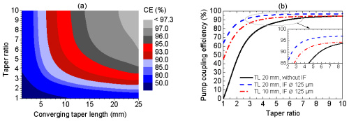
The pump coupling efficiency in dependence of the converging taper length (TL) and the taper ratio (TR) of the IF for a 1064nm high power isolator with an NA of 0.22 is depicted in Fig. 2(a)

pump coupling efficiency

Fig. 2 (a) Pump coupling efficiency (CE) with respect to the taper ratio (TR) and the converging taper length (TL) and (b) a comparison of the pump coupling efficiencies without intermediate fiber (IF) and with IF for different fiber parameters, IF Ø: IF cladding diameter.

. The simulations show that an increasing TL leads to higher coupling efficiencies at a constant TR. For example at a constant TR of 6 a TL of 5 mm leads to a theoretical maximum pump coupler coupling efficiency of 86%, whereas for a TL of 20 mm 96.4% were calculated. Furthermore, Fig. 2(a) shows that the TR can be reduced, if the TL is increased to maintain a certain coupling efficiency level. For instance, for a TL of 20 mm, a coupling efficiency of 85% can already be obtained at a TR of 2 instead of a TR of 5.5 at a TL of 5 mm. The improved coupling behavior at longer TLs can be explained by the increasing number of bounces of the pump light rays at the lateral surface of the converging taper portion. Hence, for shorter TLs it is necessary to taper more than for longer TLs in order to compensate for the shorter interaction length of the converging taper portion with the TF. The maximum theoretically obtainable pump coupling efficiency was limited to 97.3% due to different loss mechanisms, which will be discussed in Section 4.3.

In the following section we discuss the impact of the intermediate fiber on the pump coupling efficiency and the taper parameters. Thus, for comparison the fiber combiner was also simulated without the IF, which means that the tapered PFF was directly connected to the TF, assuming the same FL and also a NA of 0.22. Figure 2(b) illustrates that the coupling efficiency can be increased and the TR reduced, if an IF is inserted between the PFF and the TF. For a TR of 2.5 at a TL of 20 mm the coupling efficiencies with and without IF are 61.2% and 90.1%, respectively. The moderate coupling efficiencies without the employment of an IF at low TR can be explained by the presence of a depressed refractive index of the cladding of the PFF, blocking the power transfer from the IF to the TF, as already discussed in Section 2. Thus, without IF, the pump light rays with a low NA cannot escape from the core of the PFF, and a considerable fraction of power will be transmitted via the diverging taper portion. A further increase of the pump light NA, due to the increase of the TR up to 10 at a TL of 20 mm for the PFF and the IF, results in a successive approximation of the Polarization Maintaining Optical Circulator efficiencies. However, even at a TR of 10 and a TL of 20 mm (with IF) a 2.5% higher pump coupling efficiency can be obtained. That means for a hypothetical available input pump power of 1 kW, a reduction in power loss of 25 W can be essential to prevent thermal damage of the fiber combiner. Additionally, it must be taken into account that a TR of 10 corresponds to a considerable reduction of the mechanical stability due to the fiber diameter tapering from 125 µm to 25 µm. Furthermore, Fig. 2(b) clearly shows that the insertion of an IF with a TL of 10 mm already yields better pump coupling efficiencies than a PFF with a TL of 20 mm, especially for low TR.

A further increase of the pump coupling efficiency up to 97.8% can be realized by inserting an IF with a TL of 20 mm and diameter of 105 µm, which is perfectly adapted to the core diameter of the PFF, and thus, no pump brightness loss occurs. Note that for all of the following simulations and experiments, we only used the fiber component containing an inserted IF with a cladding diameter of 125 µm.

4.2 Simulations for the impact of the pump light input NA on the pump coupling efficiency

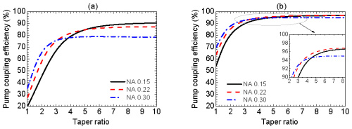
In the next simulation step we figure out, how the pump coupling efficiency changes with the pump light input NA depending on TR and TL. For these simulations three types of PFFs with a core NA of 0.15, 0.22 and 0.30 were investigated, assuming for each PFF a fully filled pump light condition. The TR was considered in the range from 1 to 10 at a TL of 5 mm

Simulations for the impact of the pump light input NA on the pump coupling efficiency

Fig. 3 Pump coupling efficiency with respect to the taper ratio at a converging taper length of (a) 5 mm and (b) 20 mm for a PFF with a pump light input NA of 0.15, 0.22 and 0.30.

) and 20 mm (Fig. 3(b)). From both figures it can be seen that at lower TRs the coupling efficiency increases with NA, since the pump light rays with a higher NA have more bounces with the lateral surface of the converging taper portion. However, the pump coupling behavior changes with increasing TR, since a TR of much higher than 2 leads to pump light rays with a NA far above 0.46, which cannot couple into the TF, if the TL is too short. The occurring pump power losses will be discussed in Section 4.3. E.g., for a low TL of 5 mm and a TR of 7 the coupling efficiency for an input NA of 0.15 was simulated to be 10% higher than for an input NA of 0.30. In contrast, with a longer TL of 20 mm the coupling efficiency seems to be less sensitive to variations of the pump light input NA. Thus, it appears that for the combiner design, the pump coupling efficiency should not be significantly influenced by the pump light input NA in the range of 0.15 to 0.30, if a sufficient TL is considered.

If the pump light input NA gets closer to the NA of the TF of 0.46, it can be advantageous to use a straight IF portion in addition to the converging taper to obtain a highly efficient pump light transfer into the TF as described in Ref [13]. An alternative approach to the straight IF portion is an increased TL, i.e. for a pump light input NA of 0.46 a theoretical pump coupling efficiency of about 90% can be achieved, if the TL is at least 40 mm.

Pump and signal combiner for bi-directional pumping of all-fiber lasers and amplifiers(2)

2. Optical design and relevant ray paths of the fiber combiner

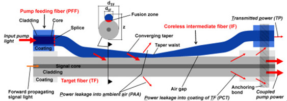
A schematic side view of the side-pump combiner consisting of a pump feeding fiber (PFF), a coreless intermediate fiber (IF) and a target fiber (TF) is shown in Fig. 1

high-power-isolator-1064nm

Fig. 1 Schematic side view of a side-pumped double-clad fiber including important ray paths.

. The diameter of the PFF core and the cladding was 105 and 125 µm, respectively. The NA of the pure silica PFF core used in the simulations was 0.15, 0.22 or 0.3 and, therefore, the refractive index of the PFF cladding was depressed in comparison to the refractive index of the PFF core. The cladding of the PFF was surrounded by a polymer coating only for mechanical protection of the fiber. Therefore, the PFF preserved the same waveguide properties after removal of the polymer coating. In the case of side-pumping without an IF, the higher refractive index of the core of the PFF would suppress the pump power transfer into the TF as long as the PFF is untapered. An increase of the NA of the pump light due to tapering of the PFF would result in an increase of the pump power transfer, though only for rays that exceed the NA of the PFF core. Thus, it is especially difficult to couple pump light rays with a low NA into the TF. Unfortunately, this type of PFF is typically used as high power delivery fiber of pump diodes. To overcome this problem, without removing the glass cladding of the PFF, a coreless IF was inserted in the fiber combiner setup. At first the ~30 cm long IF with a cladding diameter of 125 µm was fusion spliced to the PFF. The IF had a NA of 0.46 due to the refractive index difference (Δn) between fused coupler silica and the outermost polymer coating. After removing the polymer coating (e.g. with acetone) along a certain section of the IF (~15 mm), the IF was individually tapered, and afterwards the converging taper portion was laterally fused with the TF. The fusion level (FL) is defined as FL=(2z)/(dIF+dTF), where dIF and dTF are the cladding diameters of the IF and the TF at a certain taper position, respectively, and z represents the distance of the fused IF and TF, as depicted in Fig. 1. The FL was experimentally determined by measuring dIF, dTF and z at different positions along the converging taper portion with an optical microscope. With this measurement an averaged very low FL of 1.99 was determined, which was also used for the simulations. The overlap area between the TF and the IF is defined as the fusion zone. In contrast to the converging taper portion, the diverging taper portion of the IF was not fused to the TF, but placed under a small angle to the fiber axis of the TF, resulting in a small air gap between the IF and the TF. The employed TF was a DC fiber with a core diameter of 25 µm (NA 0.06) and a cladding diameter of 250 µm (NA 0.46). The cladding of the TF was also surrounded by a polymer coating, except along the coupling region of the combiner. The low index coating had to match the mechanical and additionally the optical properties of the DC fiber. An anchoring bond was used to fix the fiber bundle on each side on a copper substrate. Figure 1 shows the anchoring bond only on the right-hand side without the copper substrate. Additionally, the anchoring bond served as a pump light stripper for rays which do not satisfy the NA criterion of the TF.

Before proceeding with a more detailed investigation with the aid of simulations in the next section, we will qualitatively discuss some important ray paths of the fiber combiner. Pump light rays guided into the PFF and entering the tapered portion of the IF increase in NA as long as the rays propagate along the converging taper. As a rule of thumb, the pump light input NA increases by a factor of the taper ratio (TR), which is defined as the ratio of the original fiber diameter to the diameter of the taper waist. Pump light coupling into the TF occurs as soon the rays enter the fusion zone. The converging taper portion increases the probability for pump light transfer into the TF, since the number of ray-bounces along the lateral surface of the IF increases. Particularly, pump light rays with a low input NA couple more efficiently due to the converging taper.

Pump light rays remaining in the IF, and consequently not coupling into the TF, can occur as transmitted power (TP: transmittedpower, Fig. 1) or power leakage into the ambient air (PAA: power leakage into the ambient air, Fig. 1). As long as the condition for internal total reflection is satisfied, the pump light rays are detected as TP, otherwise the rays escape into the ambient air as PAA. The angle of total internal reflection for the uncoated IF is 43.6°, since Δn between fused silica and air is 0.45 at a wavelength of 976nm pump laser protector, which means the IF can guide light up to a theoretical NA of 1.05. Of course, the NA cannot exceed 1.0. Therefore, pump light rays with a theoretical NA in the range of more than 1.0 up to 1.05 would experience total reflection in the case of an existing fiber endface. Pump light rays which exceed the theoretical NA of 1.05 occur as PAA.

For almost loss-free pump light coupling into the TF it is necessary that the rays enter the TF before they exceed the cladding NA of the TF of 0.46. This desired coupling behavior can usually be achieved by adapting the taper parameters. However, pump light coupling for rays with an NA far above 0.46 cannot be completely suppressed. Unfortunately, this pump power leakage couple into the coating of the TF (PCT: power leakage into the coating of the target fiber) and can damage it.

In summary, the input pump combiner will be divided into the coupled pump power and the losses including PAA, PCT and TP (Fig. 1).

What is Passive Optical Network?

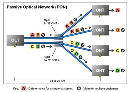
Passive Optical Network (PON) is a form of fiber-optic access network that uses point-to-multipoint fiber to the premises in which unpowered optical splitters are used to enable a single optical fiber to serve multiple premises. A PON system consists of an OLT at the service provider’s central office and a number of ONU units near end users, with an ODN between the OLT and ONU. PON reduces the amount of fiber and central office equipment required compared with point-to-point architectures.

PON Optical Network
Passive Optical Network (PON)

The most obvious advantage of the PON network is the elimination of the outdoor active devices. All the signals processing functions are completed in the switches and the user premises equipment. The upfront investment of this access methods are small, and the most funds investment is postponed until the user really access. Its transmission distance is shorter than the active optical access system. The coverage is also smaller, but it is low cost, no need to set the engine room, and easy to maintain. So this structure can be economically serve for the home users.

PON Development Background

Seen from the entire network structures, due to the larger numbers of laying optical fibers, and widely applications of DWDM technology, the backbone network has been a breakthrough in the development. The same time, due to advances in Ethernet technology, its dominant LAN bandwidth has increased from 10M, 100M to 1G or 10G.. At present, what we are concerned about is the part between the network backbone and local area networks, home users; this is often said that the “last mile”, which a bottleneck is. Must break this bottleneck, may user in the new world of the online world. It is as if in a national highway system, trunk and regional roads have been built in the broad high-grade highway, but leads to the families and businesses of the door was still narrow winding path, the efficiency of the road network cannot play.