Multiplexer and demultiplexer

In telecommunications and computer networks, multiplexing (muxing) is a method by which multiple analog message signals or digital data streams are combined into one signal over a shared medium. The goal is to share an expensive resource. For instance, in telecommunications, several telephone calls may be carried using one wire.

The multiplexed signal is transmitted over a communication channel, which may be an actual transmission medium. The multiplexing divides the capacity from the high-level communication channel into several low-level logical channels, one for every message signal or data stream to be transferred. A reverse process, known as demultiplexing, can extract the original channels around the receiver side. A tool that performs the multiplexing is known as multiplexer (Mux), along with a device that performs the reverse process is called a demultiplexer (Demux).

In electronics, a multiplexer is really a device that selects one of several analog or digital input signals and forwards the selected input right into a single line. A multiplexer of 2n inputs has n select lines, which are used to select which input line to send towards the output. Multiplexers are mainly used to increase the quantity of data that can be sent within the network within a specific amount of time and bandwidth. A multiplexer can also be called a data selector. An electronic multiplexer makes it possible for several signals to share one device or resource. Conversely, a demultiplexer is a device going for a single input signal deciding on one of several data-output-lines, which is connected to the single input. A multiplexer is often combined with a complementary demultiplexer on the receiving end. A digital multiplexer can be viewed as like a multiple-input, single-output switch, and a demultiplexer like a single-input, multiple-output switch. The schematic symbol for a multiplexer is an isosceles trapezoid with the longer parallel side containing the input pins and also the short parallel side containing the output pin. The schematic around the right shows a 2-to-1 multiplexer on the left and an equivalent switch on the right. The sel wire connects the specified input towards the output.

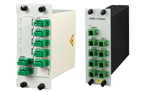
In the fiber optic area, a WDM system also utilizes a multiplexer in the transmitter to join the signals together, and a demultiplexer in the receiver to separate them apart. WDM systems are divided into different wavelength patterns, CWDM and DWDM. There are different Mux Demux for every of these.

The DWDM equipment, a DWDM multiplexer, actually contains one wavelength converting transponder for every wavelength signal it’ll carry. The wavelength converting transponders get the input optical signal, convert that signal into the electrical domain, and retransmit the signal utilizing a 1550 nm band laser. Additionally, it contains an optical multiplexer, which takes the different 1550 nm band signals and places them onto a single fiber. And also the DWDM demultiplexer breaks the multi-wavelength signal back into individual signals and outputs them on separate fibers for client-layer systems to detect. DWDM Mux and DWDM Demux are designed to multiplex DWDM channels into one or two fibers. The most popular configuration is 4, 8, 16 and 32 channels. The DWDM modules passively multiplex the optical signal outputs from 4 or more electronic devices, send on them a single optical fiber and then de-multiplex the signals into separate, distinct signals for input into electronics in the opposite end from the fiber optic link.

At the same time frame, there are CWDM multiplexer demultiplexer (CWDM Mux and CWDM Demux). They’re made to multiplex multiple CWDM channels into a couple of fibers. The core of CWDM Module application may be the passive Mux/Demux unit. The most popular configuration is 4, 8, and 16 channels. Optional wide band port for existing 1310nm or 1550nm port is available to multiplex with these CWDM Channels. Along with the CWDM transceiver series or the wavelength converter series, the bandwidth of the fiber may be used in a economical way.
CWDM/DWDM Integration

CWDM/DWDM Integration

DWDM-CWDM integration – an easy-to-realize expansion of existing CWDM systems

CWDM/DWDM

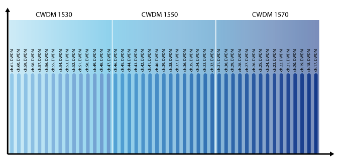
The difference between CWDM and DWDM lies in the channel spacing between neighbored wavelengths, for CWDM 20 nm and for DWDM 0.8/0.4 nm (using 100 GHz/50 GHz grid). Pan Dacom Direkt utilizes this advantage for an efficient CWDM/DWDM integration. Thereby up to sixteen DWDM channels are transmitted simultaneously in only one CWDM channel (1530 nm and 1550 nm). Thus an easy-to-realize channel extension can be achieved under continued use of existing CWDM components and thereby garantuees a protection of investment.

CWDM-DWDM integration – an easy-to-realize expansion of existing CWDM systems

What is DWDM

DWDM (Dense Wavelength Division Multiplexing)

DWDM definition:

Up to 40/80 wavelength over one pair of fiber

DWDM highlights

DWDM
DWDM
  • Up to 90 DWDM wavelength over one pair of fiber
  • DWDM channel spacing 0.8 nm (100 GHz grid) or 0.4 nm (50 GHz grid)
  • Distances over 1,000 km can be achieved with the use of optical amplifier
  • DWDM wavelength: 1528 nm (channel 61) to 1563 nm (channel 17)


DWDM principle

The functionality of DWDM resembles to the one of CWDM. Unlike to CWDM technology, the channel spacing for DWDM is 0.8/0.4 nm (100 GHz/50 GHz grid). This small channel spacing allows to transmit simultaneously much more information.Currently a restriction on wavelengths between 1530 nm and 1625 nm exists which corresponds to the C and L band. In this connection DWDM wavelengths from DWDM technology is more expensive compared to CWDM caused by the need of more sophisticated transceivers.

DWDM
DWDM


What is CWDM

CWDM (Coarse Wavelength Division Multiplexing)

CWDM definition: Up to 16 different wavelength over one pair of fiber.

CWDM highlights

Up to 16 wavelength over one pair of fiber

  • DWDM channel spacing 20 nm, 1720 nm to 1610 nm
  • Distances up to 120 km
  • Cost-effective WDM solution
  • Scalable by hybrid CWDM/DWDM – perfect solution for your investment


CWDM principle

CWDM
CWDM

CWDM is a wavelength multiplexing technology for city and access networks. Transmission is realized using 16 channels with wavelengths between 1270 nm and 1610 nm. Due to the channel spacing of 20 nm cost-effective lasers can be used. The channel width itself is 13 nm. The remaining 7 nm is designed to secure the space to the next channel.

What is WDM?

The IT refers to a medium where information is transmitted via a link. If two locations want to communicate with each other, one link is sufficient. To connect more locations more links are required What if only one link e.g. between two cities is available, but more applications shall be connected? Using the WDM technology, fiber optic links can be utilized for data transmission more efficiently.

WDM basics

The idea of xWDM technology

Each application is allocated to a dedicated color (wavelength) to communicate with a remote station. The advantage is that different colors can be simultaneously transmitted using one pair of fiber. For this purpose a multiplexer combines all different colors which will then be transmitted to the remote station over one pair of fiber. At the remote site the combined signal is separated again into different colors by a demultiplexer. Generally only one light beam with one wavelength is transferred over a pair of fiber. The wavelength multiplexing technology provides the ability to transmit more light beams, each having different wavelengths, using the same optical link. Due to the fact that wavelengths do not interfere, single light beams can be separated from each other using simple filters. A laser serves as the source of light and light-sensitive diode as receiver unit. Wavelength multiplexing is differentiated in CWDM (Coarse Wavelength Division Multiplexing) and DWDM (Dense Wavelength Division Multiplexing) technology. Advantage: With the use of WDM, it is possible today to transfer nearly 1 Tbps (C-band) via one pair of fiber.