4.3 Simulations for the loss mechanism of the fiber combiner
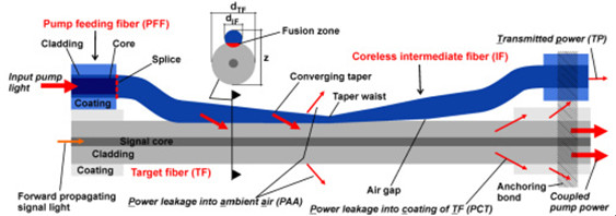
As already discussed in Section 2, the total 1064nm high power isolator loss is the sum of TP, PAA and PCT (Fig. 1). In this section we will quantitatively determine the power fraction of the different loss mechanisms to gain a better estimate of the resulting thermal load of the fiber combiner. To understand this approach, we first discuss the effect of the different loss mechanisms. The TP pump power loss is less critical, because this power fraction can be easily removed from the fiber component via the IF. The PAA is also less critical, since this power fraction can be handled by an air or 100W 1064nm high power isolator housing. The most critical pump power loss, PCT, is caused by NA-mismatched light, which couples into the coating of the TF and damages the fiber coating at a certain power level.

Fig. 4 The loss mechanism and the total pump power loss of the fiber combiner for (a) a TL of 5 mm and (b) a TL of 20 mm at different taper ratios. The losses in percent were calculated with respect to the total input pump power. Please see Fig. 1 for TP, PCT and PAA.
and 4(b) shows the three different pump power losses (TP, PAA, PCT) and the total pump power loss as a percentage of the input pump power for TL of 5 and 20 mm, depending on the TR. In the simulations the core NA of the PFF was 0.22 and fully filled pump light condition of the PFF core was assumed. It should be noted that for comparison, the axis of ordinates in Figs. 4(a) and 4(b)are scaled differently for a more comprehensive presentation of the results. In general, it can be seen that the total and individual losses are larger for a TL of 5 mm compared to a TL of 20 mm. For both TLs it turns out that the TP-fraction decreases and the PCT-fraction as well as the PAA-fraction increases with TR. As a result, the total power loss decreases with increasing TR. A closer analysis of the PCT-curve reveals that PCT loss does not exist below a TR of 2, since the 3 Port Polarization Maintaining Optical Circulator input NA of 0.22 will be approximately increased by the factor of the TR [18], and therefore cannot exceed the cladding NA of the TF of 0.46. Thus, the fraction of PCT can be reduced by choosing a low TR with a still acceptable total power loss. This means that the TR must be carefully adapted to satisfy the trade-off between a high pump coupling efficiency and a low power fraction of PCT to avoid optically induced damage of the fiber component during high power operation. This must always be accompanied by a sufficient converging taper length.
For example, if the TR is set to 7 for a TL of 5 and 20 mm, respectively, the theoretical PCT is 7.7 and 1.2% of the input pump power. The PCT value of 1.2% at a TL of 20 mm can be further reduced to 0.6% by changing the TR from 7 to 4 in conjunction with an acceptable total power loss of just 5%. Hence, if 1 kW of input pump power is assumed, the resulting power handling for the coating of the TF and the pump light stripper can be reduced from 77 W (TL 5 mm, TR 6) to 6 W (TL 20 mm, TR 4) by adapting the TL and the TR.
The simulations indicate that the minimum total power loss cannot be reduced below 2.7% for a TL greater than 20 mm up to a TL of 50 mm and a FL of 1.99. One reason for the residual losses can be pump light rays with a Polarization Maintaining Fused Coupler, which propagate along an unfavorable plane of the IF and do not enter the fusion zone. These rays leave the waveguide (PAA) structure after sufficient bounces along the lateral taper surface. In addition, rays with an extremely low NA, and consequently less bounces with the lateral surface of the converging taper portion, can occur in the form of TP. Furthermore, longer TLs lead to an increased probability that some rays will reverse couple from the TF into the IF.
Moreover, the simulations reveal that a lower FL-value, which means stronger fusing of the fibers, leads to a decrease of the total power loss. The exact reduction of the total power loss depends on the fiber and taper parameters. For a TL of 20 mm and a TR of 6, the simulated total power losses could be reduced from 4% to 2% when decreasing the FL from 1.99 to 1.93. The simulations indicate that for FLs below 1.93 the total power loss increase again.
4.3.1 Impact of pump light input NA on the power leakage into the coating of the TF (PCT)
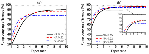
The simulations in Section 4.2, Fig. 3(b) showed that a sufficient TL leads to pump coupling efficiencies of more than 90%, almost independent of the pump light input NA. Considering the losses, the simulation also shows that the PCT-fraction is strongly influenced by the pump light input NA. Figure 5
Fig. 5

(PCT) to the total input pump power against the taper ratio for a TL of 20 mm.
clearly reveals that for a TL of 20 mm and a TR of 6, the PCT-fraction increases by about 6 times for a NA of 0.3 compared to a NA of 0.15. Hence, it is possible to achieve almost the same coupling efficiency for a pump light input NA of 0.15 and 0.3 (see Fig. 3(b)), but with a significant difference in risk of optically induced damage to the fiber component. However, PCT can be further reduced by increasing the TL.


