The Ion exchange process and the Glass choice of the PLC Splitter Chip

Along with development of the optical communication, its good environmental stability and compatibility with fiber, began to widely used optical communication components manufacturing.( Such as self-focusing lens, optical divider, optical amplifier, etc), And extend to the sensing area, (such as: all kinds of biological and chemical sensors , current sensors which is based on fading light waves, etc.)plc splitter

Glass ion-exchange technology has several one hundred years long history, Its earliest used to change the light absorption characteristics of glass, glass coloring,then, the technology is widely used in processing on the surface of the glass surface (such as touch screen add hard processing). Along with development of the optical communication, its good environmental stability and compatibility with fiber, began to widely used optical communication components manufacturing.( Such as self-focusing lens, optical divider, optical amplifier, etc), And extend to the sensing area, (such as: all kinds of biological and chemical sensors , current sensors which is based on fading light waves, etc.)

Current mainstream technology of PLC Splitter chip includes: PECVD technology, flame hydrolysis technology, glass ion exchange technology. Glass principle and technological process of ion exchange technology as shown in figure 1,figure 2. The main process flow flame hydrolysis technology shown in figure 3. The process characteristics of contrast see table 1. From years of use and reliability experiment, the two technologies are used in mass production and the performance is good.The features of PECVD/flame hydrolysis technique are that equipment and raw materials is the existing material, but its process is very complicated, the production cycle is long, the processing tolerance is small; Glass ion exchange technology is characterized by equipment and raw materials need special customized, but its technology is relatively simple, high production efficiency, process tolerance is larger, the chip cost is relatively low.

DK Photonicswww.dkphotonics.com  specializes in designing and manufacturing of high quality optical passive components mainly for telecommunication, fiber sensor and fiber laser applications,such as PLC Splitter, WDM, FWDM, CWDM, DWDM, OADM,Optical Circulator, Isolator, PM Circulator, PM Isolator, Fused Coupler, Fused WDM, Collimator, Optical Switch and Polarization Maintaining Components, Pump Combiner, High power isolator, Patch Cord and all kinds of connectors.

Planar Lightwave Circuit (PLC) Splitters Market Forecast

Telecommunication applications dominate the worldwide PLC splitter marketplace…

ElectroniCast Consultants, a leading market/technology consultancy, today announced the report release of their market forecast of the global consumption of Planar Lightwave Circuit (PLC) splitters used in Fiber Optic Communication Networks.

This ElectroniCast study report details of last year’s consumption and forecasts to the year 2017 of PLC splitters by product-level (level of fabrication), in selected optical communication applications.   There are actually three (3) separate market forecasts:

According to ElectroniCast, the PON, FTTx, and Telecommunication network applications dominate the worldwide PLC splitter compact device consumption value in 2012 with 77% in relative market share; followed by the cable TV segment, the PLC splitters used in Test/Measurement applications and then Harsh Environment (Military/Aerospace, Industrial) and finally Private Enterprise Networks.

In the report, ElectroniCast provides their market data covering the following optical communication applications:

  • Passive Optical Network (PON) / FTTX / Telecommunication Networks
  • Cable TV (CATV)
  • Fiber Optic Test/Measurement
  • Private Enterprise/Data Centers/Local Area Networks (LANs)
  • Harsh Environment (Military, Industrial, Other)

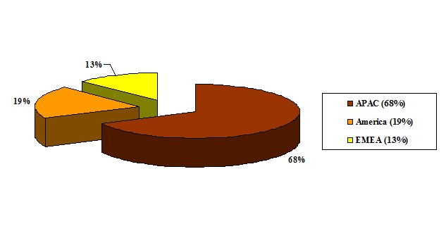
In 2012, the Asia Pacific region (APAC) region leads in the consumption of PLC splitter compact devices with 68% of the worldwide value, followed by the American region and finally the EMEA region.

According to ElectroniCast, the Asia Pacific region dominates the worldwide value of PLC splitters with 68% in 2012…

PLC Splitter Component-Level Compact Devices

2012 – Global Consumption Value Market Share (%), by Region

 (Source: ElectroniCast Consultants)

 PLC

DK Photonicswww.dkphotonics.com  specializes in designing and manufacturing of high quality optical passive components mainly for telecommunication, fiber sensor and fiber laser applications,such as PLC Splitter, WDM, FWDM, CWDM, DWDM, OADM,Optical Circulator, Isolator, PM Circulator, PM Isolator, Fused Coupler, Fused WDM, Collimator, Optical Switch and Polarization Maintaining Components, Pump Combiner, High power isolator, Patch Cord and all kinds of connectors.

DWDM multiplexer and CWDM mux

As the DWDM mux/demux & CWDM mux/demux goods are playing an even more and more important role inside the data transmission field, today organic beef focus on the key options that come with DWDM mux and CWDM multiplexer first.

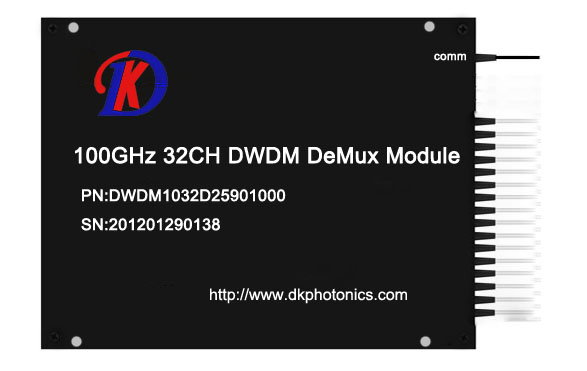
100G_32ch DWDM Module
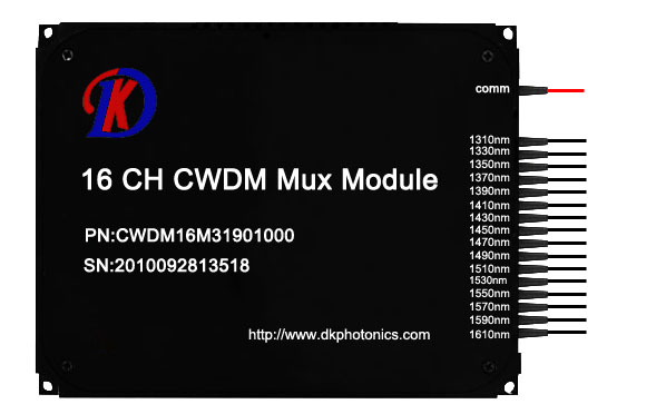
16CH CWDM Mux Module

As everybody knows, DWDM which represents Dense Wavelength Division Multiplexing was created to multiplex DWDM channels into one or two fibers. This sort of products could make the optimum usage of your existing fiber optic infrastructure in an ideal way. It puts multiple signals together and sends them simultaneously along a fiber, simply with transmissions happening at different wavelengths, and also this turns an individual fiber to the virtual equal of a handful of fibers. It is really a good and also the most reasonable solution to date that will meet our increasing desires of large data transmissions. And also by using the impressive DWDM technique, it will transmit greater than 40 connections of numerous standards, data rates or protocols more than one common fiber optic link. For the DWDM products, the DWDM mux products combine several data signals into one for transporting on the single fiber as the DWDM demux (demulitplexers) separate the signals on the opposite end. Each signal reaches a different wavelength, they cooperate with each other perfectly.

The common configuration of DWDM mux is 4, 8, 16 and 32 channels. These DWDM modules passively multiplex the optical signal outputs from 4 or maybe more electronic devices, send on them an individual optical fiber and then de-multiplex the signals into separate, distinct signals for input into electronic devices in the opposite end with the fiber optic link.

The DWDM mux products always own these following features.

1.Low insertion loss and high isolation.

2.Simple to install, requires no configuration, and disassembles easily to clean.

3.Fully transparent at all data rates and protocols.

4.Completely passive, no power required, no cooling and so on.

And for the CWDM multiplexer, the core of CWDM Module application will be the passive mux/demux unit. The most popular configuration is 4 , 8 ,16 channels. Available in 19″ Rack Mount or LGX module package. Optional wide band port for existing 1310nm or 1550nm port is available to multiplex using these CWDM Channels. As well as our CWDM Transceiver series or perhaps the wavelength converter series, the bandwidth with the fiber can be employed in the economical way. The CWDM multiplexer is always be employed to improve your fiber capacity easily and quickly.

As the very best Chinese fiber optic products supplier, DK Photonics provides lots of this sort of products which are reliable and economical. If you may well not find it on our website (what we upload is the mux & demux inside a device), you can call us to customize it to suit your needs. For standalone multiplexers, it could increase dual fiber link capacity up to 18 channels and could be combined with a lot of the CWDM GBIC, SFP, XFP, X2, XINPAK, SFP modules. It’s also super easy to make use of and install, and also have some common features because the DWDM mux. Now it’s prepared to do the job, please do not hesitate to make contact with us. Thank you for visiting contact the DK Photonics representatives for more information if you need good quality and cost-effective DWDM mux and CWDM multiplexer products.

Application of Optical Add/Drop Multiplexer CWDM/DWDM Module

What’s the CWDM/DWDM Optical Add-drop Multiplexer?

The optical add-drop multiplexers (OADM) are used in wavelength-division multiplexing systems for multiplexing and routing different channels of light into or out of a single mode fiber. This is a type of optical node, which is generally used for the construction of optical telecommunications networks. An OADM may be considered to be a specific type of cross connect cabinet.

OADM ModuleOADM Module Application of OADM

A traditional OADM consists of three stages: an optical demultiplexer, and optical multiplexers, and between them a method of reconfiguring the paths between the optical demultiplexer, the optical multiplexer and a set of ports for adding and dropping signals. The optical demultiplexer separates wavelengths in an input fiber onto ports. The reconfiguration can be achieved by a fiber patch panel or by optical switches which direct the wavelengths to the optical multiplexer or to drop ports. The optical multiplexer multiplexes the wavelength channels that are to continue on from demultiplexer ports with those from the add ports, onto a single output fiber.

Principles of OADM technology

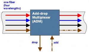
General OADM node can use four port model (Figure 1) to represent, includes three basic functions: Drop required wavelength signal, Add rumored signal to other wavelengths pass through unaffected. OADM specific network process is as follows: WDM signal coming from the line contains mangy wavelength signals into OADM’s “MainInput” side, according to business required, from many wavelength signals to selectively retrieved from the end (Drop) output desired wavelength signal, relative to the end from the Add the wavelength of the input signal to be transmitted. While the other has nothing to do with the local wavelength channels directly through the OADM, and rumored signals multiplexed together, the line output from the OADM (Main Output) Output.

OADM node technical classification

Optical drop multiplexer network technologies can be divided into two types, fixed optical drop multiplexer (Fixed OADM, FOADM) and reconfigurable optical drop multiplexer (Reconfigurable OADM, ROADM).

Fixed Optical Drop Multiplexer (FOADM)

FOADM to filter as the main component, and its function is fixed to join or retrieve certain light wavelengths. General common FOADM can be divided into three types, namely Thin Film Filter type (TFF type), Fiber Bragg Grating (FBG type) and integrated planar Arrayed Waveguide Gratings (AWG type).

* TFF FOADM using thin film between the filtering effect of the different refractive index.

* FBG FOADM use of fiber Bragg grating filtering effect, with two circulator can become FOADM.

* AWG FOADM gererally used in semiconductor fabrication processes, the integration of different refractive index material is formed on a flat substrate in a planar waveguide, when different wavelength light source is incident through the couping after the import side, due to take a different path length, while the different phase delay caused by different wavelengths and thus produce certain wavelengths in the export side to form a constructive or destructive interference, making waves in the export side, the different wavelengths will follow the design on a different channel to reach, and thus achieve FOADM function.

Reconfigurable Optical Add/Drop Multiplexer (ROADM)

ROADM can always be adjusted with the distribution network to add and drop wavelength, which reconstruct the network resource allocation, the flexibility to meet the requires of modern urban network, so a flexible ROADM features, plus optical switch substantial advantage, making the current fastest growing ROADM based optical switches based ROADM (switch based OADM). ROADM mainly be the optical switch, multiplexer and demultiplexer composed, Switch-based OADM, mainly divided into Wavelength independent switch array and wavelength selection switch.

OADM network applications

WDM ROADM optical fiber suitable for different network environments.

OADM in the metropolitan network development tendency

1. Arbitrary choice must be retrieved, adding wavelength, the wavelength can take advantage of the limited resources, the node can be retrieved with the need to do to join the adjustment of the signal wavelength, and has a remote control functions. This can provide dynamic reconfiguration of optical communications network capable ROADM will be connected to the backbone network critical devices. And FOADM is used for wavelength demand network access will be smaller parts to reduce costs. Furthermore, ROADM use to all kinds of Tunable Laser, unable Filter, or wavelength selective optical switches and other components.

2. Must be able to convert incompatible wavelength suitable for the backbone network will be transmitted wavelengths. Therefore, OADM be combined with wavelength conversioin Transponder or other functional components.

3. Must be able to compensate for the node to make acquisistion, adding such action energy loss. Therefore, OADM optical amplifiers must be combined with functional components.

4. Wavelength signals related specifications, such as: the signal to noise ratio (S/N), the energy balance between the signal wavelength, etc., are required to meet network requirements. Therefore must be combined OADM variable optical attenuators (VOA), dispersion compensation module (DCM) and other components.

Application of fiber optic high power isolator and some mutual problems about its production process

1 introduction

Semiconductor lasers, optical amplifiers and optical fiber lasers from the connector, fusion point, filter the reflection light is very sensitive, and may cause performance deterioration and even damaged, requiring a optical isolator to prevent the reflection of light. The optical isolator is permitted only light along one direction through and in the opposite direction blocks light through the optical passive devices. In the optical fiber communication, optical fiber reflection light through the optical isolator can be a good isolation. In the fiber laser applications, optical isolators are usually used in the optical path to avoid the light path of the light source, the echo on the pumping source and other light emitting device causes interference and damage. Isolators’s isolation represents the optical isolator to echo the isolation (blocking) ability.

2 optical isolator principle

Optical isolator using magnetic optical crystal Faraday effect ( also known as the Faraday effect ). In 1845, Faraday first observed with optical material under the action of magnetic field to make the material in the direction of polarization rotation, therefore often called the Faraday effect. In Faraday effect, the rotation of the polarization direction direction and magnetic field, and the orientation of the light transmitting is independent of the forward and reverse, and we usually in the index of refraction, reflection phenomena seen in the reversibility of optical path difference. Along the magnetic field direction of transmission line polarized, the polarization direction rotating angle θand magnetic field strength of B and L is proportional to the product of the length of the material, the proportion coefficient is what we often say that the Wilde constant. Optical isolator based on polarization characteristics can be divided into polarization-independent and polarization dependent type. These two kinds of isolators are used with the Faraday effect in magneto-optic crystal, Faraday magnetic medium in 1~2μ m wavelength range usually adopts the optical loss low yttrium iron garnet ( YIG ) single crystals. Model of input and output of the fiber optical isolator has fairly good performance, the minimum insertion loss of approximately 0.5 dB, the isolation of up to 35~ 60 dB, a maximum of 70 dB.   The optical isolator using most still is polarization independent type, its principle is shown in Figure 1, using the forward and reverse transmission optical path is inconsistent, it is this time signal transmission is not reversible, thereby forming isolation. The typical structure of only four major components: the magnetic ring, a Faraday rotator, two pieces of LiNbO3 wedge angle piece, with a pair of fiber collimator, can be made into an in-line optical isolators.

Positive transmission: the parallel light beam from the collimator, into the first wedge angle piece P1, beam is divided into o light and e light, the polarization direction perpendicular to the propagation direction, forming an included angle. When they pass through 45o Faraday rotator, emitted by the o light and e light polarizing surfaces of respective to the same direction of rotation 45o, because the second wedge-shaped plate P2 crystal axis relative to the first wedge angle piece is just in a 45o angle, so o light and e light is refracted into a small space, synthesis. Parallel light, and then by another collimator is coupled to the optical fiber core. In this case, the input optical power only a very small fraction of outage, this loss is called isolator insertion loss.

Reverse transmission: when a beam of parallel light reverse transmission, first with a P2 crystal, divided into the polarization direction and P1 crystal axis respectively in 45o angle o light and E light. Due to the Faraday effect non reciprocity, O Light and e light through the Faraday rotator, the polarization direction to the same direction of rotation 45 °, so the original o light and e light in the second wedge-shaped plate ( P1 ) later became e and O light. Because the refractive index differences, the two light beam in the P1 no longer possible synthesis of a parallel beam of light, but in different directions to the refraction of light, e and o are further separated from a larger perspective, even after a GRIN lens coupling, can not enter the fiber core to, from and achieved reverse isolation purposes. The transmission loss is bigger, this loss is called isolators isolation.

3 main technical parameters of optical isolator

The optical isolator, the main technical indicators have insertion loss, reverse isolation, return loss, polarization dependent loss, polarization mode dispersion.

(1) insertion loss ( Insertion Loss ): isolator core mainly comprises a Faraday rotator and a two piece of LN wedge angle piece, a Faraday rotator extinction ratio higher, lower reflectivity, absorption coefficient is smaller, insertion loss is smaller, general Faraday rotator loss is about 0.02~ 0.06dB. Parallel light pass through the isolator core, will be divided into o, e beams of parallel light. Due to the inherent characteristics of birefringent crystals, O Light and e light can not fully converge, which may cause additional insertion loss.

(2) reverse isolation ( Isolation ): reverse isolation isolator is one of the most important indicators, which characterizes the isolator on the reverse transmission attenuation ability. Effect of isolator isolation of many factors : 1 ) the isolation and polarizer from the Faraday rotator is related to the distance; 2) isolation and optical element surface reflectance relationship. Isolator optical element surface reflectance is bigger, the isolation degree is worse. The practical technology that R must be less than 0.25%, to ensure the isolation degree is greater than 40 dB; 3) isolation of polarimeter and wedge angle, spacing. Double refraction crystal yttrium vanadate ( YVO4 ) of the optical isolator, when the wedge angle of less than 2°, isolation with the perspective of the increase, when the wedge angle is greater than 2°, change is much smaller, approximately stable at about 43.8 dB. Optical isolation with the increase of the distance between the change range is not big, because isolation depends mainly on the reverse output light and the angle between the optical axis; 4) isolation and crystal axis angular relationship relative. The two polarizers and rotator crystal axis relative angle to the isolation effect is maximum, when the angle is greater than the difference between the 0.3o isolation will not be greater than 40 dB; 5) the two polarizer extinction ratio, crystal thickness on isolation effect; 6) the influence of temperature and magnet. In Faraday effect, Verdet constant is a function of temperature, so the Faraday rotation angle will change with the temperature, and the temperature will be on permanent magnet performance impact, so it is one of important factors.

(3) return loss ( Return Loss ): optical return loss refers to the positive incident to the isolator optical power and along the input path to return to the isolator input port of the optical power ratio, this is one of the important indicators, because the echo intensity, isolation would be affected by. Isolator echo loss by each element and the air refractive index mismatch caused by the reflection. The generally planar element caused by echo return loss is controlled in 14 dB, through antireflective film and surface polishing can make the return loss reached more than 60 dB. Optical return loss mainly from the collimated light path (i.e., collimator parts), through the theoretical calculation when the slant angle 8 °, return loss is greater than 65 dB.

(4) the polarization-dependent loss ( Polarization Dependent Loss, PDL ) :PDL and insertion loss is different, it is a when the input light polarization state changes and other parameters unchanged, the insertion loss of maximum variation, is a measure of device insertion loss by effect of polarization degree index. The polarization-independent optical isolator, the device has some may cause polarization components, impossible to achieve PDL is zero, a generally accepted PDL is less than 0.2 dB.

(5) the polarization mode dispersion ( Polarization Mode Dispersion, PMD ) :PMD is defined through the device of the signal light with different polarization states of the phase delay between, in high speed optical communication system is very important in PMD. In optical passive devices, different polarization modes have different propagation paths and different propagation speed, produce corresponding polarization mode dispersion. At the same time, because the light source spectrum lines have a certain bandwidth, can also cause certain dispersion. In a polarization-independent optical isolator, birefringent crystal to produce two beams linearly polarized light in different phase velocity and group velocity of transmission, which is PMD, its main source is used for separation and convergence o light and e light of birefringent crystal. It can be made of two linearly polarized optical path differenceΔ L approximation. PMD is mainly affected by E and O optical refractive index difference, therefore also has great relationship with wavelength.

4 key technologies of high power isolator

Compared with the common optical fiber communication system in the use of low power optical isolator is compared, in the high power laser, optical isolator design and production also exhibit differences, it is also in high power device is designed to solve the main problems in the development of.

(1) the optical element at a high power density laser radiation damage problems. Not only is this problem in a high power optical isolator in existence, is the other high power optical device design process is also to face. In order to solve this problem, first of all need to products in the production and testing process to ensure good environmental cleanliness and selects the damage threshold of high optical device and optical thin films, of course it is cost constraint. Because the air in the tiny particles if adhesion in optical surface will greatly reduce the laser damage threshold of optical surface, these tiny particles on laser absorption is relatively large, easily lead to particle near the energy is concentrated, resulting in optical surface film damage even surface damage, the element surface pitting and even small pit to device failure. Secondly, because in most cases within the optical element damage threshold than the surface laser damage threshold is much higher, so the surface of the laser power density is determined by the whole device resisting laser damage ability, especially in the pulse work situation is even more so. This can be through optical transform method to make optical element surface spot area expansion method to increase the damage threshold, such as expanded core fiber and beam expanding lens optical method is the use of the principle of work, or by changing the laser pulse stretching method to reduce the power density of laser, laser energy in space and by avoiding time of concentration can effectively improve product for resisting laser damage properties.

(2) the high power device for thermal effects and thermal design. Because of the high power device to work in a higher power, and low power devices compared, easy fever, inevitably subjected to temperature rise, so the device performance by the thermal characteristics and thermal design to compare the effects of severe. Usually the optically active crystal optical rotation characteristic of easily affected by temperature, if the device is operating due to the absorption of laser energy accumulation and lead to internal temperature appears bigger rise, will make the optically active crystal on light polarization plane rotation angle deviations from normal values and lead to significant performance loss, serious and even lead to damaged devices; in addition, the permanent magnet at work under high temperature but also more prone to field weakening and demagnetization phenomenon, appear even the magnetic field of the irreversible loss, so the high temperature to the permanent magnet steady work is negative; and, in case of high optical power, optical element temperature will appear bigger rise, due to heat from the inside to the conveying surface, its internal the temperature is above its surface temperature, so that it will in the optical component internal temperature gradient and thermal stress, causing the beam cross-sectional internal center of the refractive index and the edge of the refractive index change in different extent, appear thereby the refractive index difference, also is the emergence of lens effect, it will change the beam propagation characteristics, leading to beam quality drops badly, seriously affect the normal work and even cause damage to device. Therefore, we must take effective measures to reduce the absorption of laser radiation and effective. To reduce the absorption of laser selected absorption coefficient smaller optical materials, Ko Hikaru in the components inside the transmission distance, reasonable structure design, effective heat dissipation requirements may arise in heat accumulation place provides effective heat transfer path and heat dissipation, according to the size of power can adopt a passive or active heat radiation method. The million kilowatts level optical isolation design on the use of the lath shape of the optically active crystal to improve device cooling temperature control ability.

(3) the magnetic field design for high power isolator. High power optical isolator design another key is the magnetic field and magnet design and selection. In general, the optical isolator is the use of magnetic rotation effect work, so must the optically active crystal with proper magnetic field. In order to energy saving and convenient use, generally by the strong permanent magnetic material to produce a desired magnetic field, the magnetic field and magnet selection and design is very important, on device performance and the cost of. Under normal circumstances required in the optically active crystal space to provide a strong homogeneous magnetic field, so it can reduce the optically active crystal size, high ratio of performance to price, so the requirement in without significantly increasing the device volume in the case of the design of suitable magnet to obtain a strong homogeneous magnetic field. In specific design, through the choice of magnetic strong magnets, and adopt suitable shape and volume, to obtain the required magnetic field

(4) High power optical isolator assembly process. High power optical isolator can work stably for a long time in bad environment, this device structure and assembly process raised very tall requirement. Design of the structure and assembly technology can effectively reduce the optical components of the internal stress, thereby improving the product performance and stability, allows the device to long-term stable and reliable work. Isolator structure design mainly need to solve two problems, first is the optical components of the assembly, stable and reliable heat dissipation requirements, can effectively control; second is firm and reliable assembly of strong permanent magnet, with the magnet design and manufacturing capabilities, devices may use more complex shape of the magnet pieces combined to provide a strong homogeneous magnetic field, between the magnets and strong magnetic requires the design of suitable assembly method and reliable assembly magnet, and required in the assembly process causes no damage or the magnet demagnetization. These need to be accumulated in practice and improve.

Above only briefly in the high power optical isolator design process often encounter some problems, along with applications to expand and deepen, may be needed for isolator corresponding improvement or design to meet the technical and market development, in this process may occur early in the design of possibly unforeseen problems, this requires us to according to the specific circumstances to provide the corresponding solutions, only in this way can we continue to design excellent performance to meet the application needs of the high power optical isolator.
How Great Of Fiber Optic Cables

Fiber optic cables are used frequently for today’s telecommunication network because of their high bandwidth, high reliability and relatively low cost. For a layman, fiber optical cable or FOCs as they are often called, is a plastic or glass fiber which permits the transmission of communications over large distances and at higher rates. They present wire almost superfluous, because they pass the same, but there are a lot of loss. These cables are unique because they are not affected by electromagnetic interference. Use these cables in performing image used in the fiber.

Each cable can not beyond the permissible limit. Fiber optic cable is very safe and more reliable than the traditional copper wire. Most of these cable to work in high-pressure environments. A fiber optic cable assembly includes a tube, a track and fasteners in addition to the conventional fiber bundles.

The cable tubes have both front and rear surfaces to it. These cables operate with the help of photons. These photos are transmitted to a second quantum dot which is placed between mirrors. These mirrors absorb the photons and bounce them back to the quantum dot until it absorbs it.

The fiber optic cables are used for carrying different services pertaining to data, voice, cable TV, and video. The fiber optic cables keeps the electronic equipments far away from environment that are subjected to high temperature, stem, dust, smoke and so on. The unique feature of these fiber optic cable is that stainless steel lens and fiber cables can be easily replaced without any further calibration.

For the installation of fiber optic cables, fiber optic cable blowers are designed. The unique feature of these fiber optic is that they carry information in the form of light. These cables are very useful in transporting both audio and video signals over short and long distances. If a fiber optic cable is broken, another cable has to be fitted in between the connectors rather than soldering or twisting them. Fiber optic technologies have found its place in many applications. They are widely used in telecommunications, CCTV security places, and local area networks and so on.

Glass fibers are made use of for fiber optic cabling. They hardly provide any change in the signals they carry over long distances. Engineers found that by adding some additional chemicals into the existing silica, they can change the properties of the glass used for the cable (glass fiber cable). Althouth, both glass and plastic can be used in the manufacture of cable, glass is the preferred one used in the manufacture of cable, used for long distance transmission communication. The purpose of glasses in total internal reflection transmission.

A fiber optic cable consists of a core which is made of glass silica. Through this core, the light is guided. The core is covered with a material whose refractive index is slightly lower than that of the core. Two optical fibers are connected via mechanical splicing or fusion splicing. This process involves lots of skills as microscopic precision is required to align them.

Regardless of the application used in optical fiber, they will stay here. Their unique features and capabilities, to ensure that they will continue to spread widely used in communications industry for many years.

What Is an Optical Attenuator?

LC Plug Type Fixed AttenuatorAn optical attenuator decreases the strength of an optical signal passing through it to a fiber optic cable or open air. The intensity of the signal is described in decibels over a specific distance the signal travels. It is the strength, or amplitude of the signal that changes and not the overall waveform or frequency, so the optical signal remains undistorted for use in the desired application. Optical attenuators are often used in optical communication systems, in which the attenuation, also called transmission loss, helps with the long-distance transmission of digital signals. The most common optical attenuator types include fixed and continuously variable attenuators.

Often installed where signals are transmitted from, an optical attenuator can apply the principle of gap loss so the signal intensity is lowered to the optimal level over a given distance. Attenuators installed elsewhere along the optical fiber will not lower the signal strength enough, but some devices utilize signal absorbing or reflecting components to compensate. An optical fiber connector is often attached to the optical attenuator which typically has an adapter with a female configuration. The attenuator itself usually has a cylindrical or even box-like structural shape which determines the type of equipment in which it can be installed.

The fixed variety of optical attenuator, sometimes found in an electronic circuit, does not reflect light signals to reduce their intensity. It is generally used where the transmission of data needs to be highly accurate. The device’s function is determined by the amount of power it can handle in addition to important variables such as performance versus temperature and frequency range. Most optical attenuators utilize resistors, but a variable optical attenuator uses metal semiconductor field effect transistors or other solid state components. Attenuation intensity is adjustable so the signals in a fiber optic communication system can be changed to accommodate fluctuating power levels, protecting the system from damage.

A variable optical attenuator can be mounted on a printed circuit board, or used in test devices such as an optical power meter. Many attenuators are installed in-line with an optical fiber cable in order to adjust the transmitted signal accordingly. They are sold by many retailers and manufacturers online so one can assess their characteristics by reading the product specifications. Aspects to consider include the average and peak power the device can tolerate, how much attenuation it provides, as well as its overall dimensions and the type of environment it can operate in.

Application of optical communication is still broad prospects

Once the Nortel global leader in fiber optic communications during the Internet bubble in 2000, the money in the acquisition of a large number of optical communications research and the production of small and medium enterprises, the industry has been criticized in the subsequent bankruptcy of Nortel. In fact, Nortel grasp of technology trends, the direction is right, unfortunately, Nortel too hasty, global demand for optical communication was not to such an extent.

But now the situation is very different compared with around 2000. The rapid development of mobile Internet and the widespread popularity of smart mobile terminal equipment, being a huge challenge to the global telecommunications network capacity, transmission speed. The era of “data flood peak to optical communication technology has always been known by the transmission bit of new development opportunities and a huge space. Optical communication technology not only did not fall behind, the contrary, the optical communication industry chain, from fiber optic cable system equipment, terminal equipment to optical devices, a critical period in the comprehensive technology upgrade.

The field of optical communication is a noteworthy event, the National Development and Reform Commission recently organizing the preparation of strategic emerging industries key products and services Guidance Catalogue, which in conjunction with the relevant departments, the optical communication technology and product responsibility and selected emerging industries of strategic focus products.

In fiber optics, including FTTx G.657 optical fiber, broadband long-distance high speed large capacity optical fiber transmission with G.656 optical fiber, photonic crystal fiber, rare earth doped fiber (including ytterbium doped fiber, erbium doped fiber and thulium doped fiber, etc.) the laser energy transmission fiber, and has some special properties of new optical fiber, plastic optical fiber, polymer optical fiber is fully finalists. The upgrade of the fiber optic technology, will bring the data transmission capacity, distance, quality leap.

In the field of fiber access equipment, passive optical network (PON), wavelength division multiplexer (WDM),OLT and ONU on the list. Optical transmission equipment, especially the line rate of 40 Gbit/s, 100Gbit/s large capacity (1.6Tb/s and abobe) DWDM equipment, reconfigurable optical bifurcation Multiplexer (ROADM) wavelength division multiplexing system ran cross-connect (OXC) equipment, large-capacity high-speed OTN optical transport network equipment as well as packetized enhanced OTN equipment, PTN packet transport network equipment also impressively. These products are “broadband China” works to promote a powerful weapon; both long-distance backbone network, metropolitan area network or access network even close to the user’s “last mile” of these products will come in handy.

The major products are classified as strategic emerging industries in the field of optical devices, high-speed optical components (active and passive). This is the core and foundation of the field of optical communication technology, device development, the improvement of integration, function enhancement can bring significantly reduce the cost of system equipment and provide a performance boost.

At the same time, the annual OFC / NFOEC (fiber-optic communications exhibition) will be held in late March in California. This event will showcase the latest technology and research progress of the global optical component modules, systems, networks and fiber optic products, represents a new trend of development of optical communication technology.

100G for ultra-high-speed network technology is the current OFC hot one. 2012 100G technology on a global scale backbone network level scale application of 100G optical network applications will rapidly expand with the 100G device further mature. In the same time, the industry has also increased efforts to develop the 100G optical modules, silicon photonics technology pluggable multi-source agreement 100G CFP MSA CPAK optical module has been available. Outside the backbone network, 100G MAN application is the current one of OFC discussion topic.

The rise of cloud computing brings data center construction boom, 100G technology in the data center is a popular data center for high-speed pluggable optical devices is also a hot topic. Experts believe that photonic technology has a key role to play in the large enterprise data centers, but this is only a start, the size of the new cloud computing data center such as a warehouse, with more than 100,000 servers carrying the computing and storage resources, the required network bandwidth than PB level. These data centers only optical communications technology in order to achieve VCSEL (vertical cavity surface emitting lasers) and multi-mode fiber has played an important role, and will continue to introduce new fiber optic communication technology.

Things You Should Know About Filter WDM

Wavelength-division multiplexing (WDM) is overtaking since the leading technology in point-to-point transmission links. One key method is a tunable optical filter. Important features of this type of filter include low insertion loss, narrow bandwidth, high sidelobe suppression, large dynamic range, fast tuning speed, a simple control mechanism, small size, and expense effectiveness. Filter WDM module will depend on Thin Film Filter (TFF) technology. The FWDM is extensively found in EDFA, Raman amplifiers, WDM networks and fiber optics instrumentation. The unit combines or separates light at different wavelengths in the wide wavelength range. Since FWDM series offer minimal insertion loss, low polarization dependence, high isolation and excellent environmental stability, perfect for very fast WDM network systems. It really is traditionally used in optical fiber systems:1310/1550nm, 1480/1550nm, 850/1310nm, 980/1550nm and 1310/1490/1550nm.

FWDM Main Features:

  •  Wide Operating Wavelength Range;
  •  Low Insertion Loss;
  •  Ultra Flat Wide Passband;
  •  High Channel Isolation;
  •  High Stability and reliability;
  •  Epoxy-free on Optical Path.
  •  FWDM Applications:
  •  Testing Instruments;
  •  FTTH Tri-Play System.

WDM is a method of combining multiple signals on lasers at various infared (IR) wavelengths for transmission along fiber optic media. Each laser is modulated by an impartial pair of signals. Wavelength-sensitive filters, the IR analog of visible-light color filters, are employed on the receiving end.

WDM is comparable to frequency-division multiplexing (FDM). But rather than going on at radio frequencies (RF), WDM is done inside the IR element of the electromagnetic (EM) spectrum. Each IR channel carries several RF signals combined by using FDM or time-division multiplexing (TDM). Each multiplexed IR channel is separated, or demultiplexed, in the original signals with the destination.

The usage of WDM can multiply the effective bandwidth of an fiber optic communications system with a large factor. However its cost should be compared to the choice of utilizing multiple fibers bundled in to a cable. A fiber optic repeater device referred to as erbium amplifier plans to make WDM a cost-effective long-term treatment for the bandwidth exhaustion problem.

DK Photonics offers a wide selection of WDM/CWDM/DWDM devices, like CWDM Mux/Demux, CWDM OADM, DWDM Mux/Demux, DWDM OADM, Filter WDM and so on. DK Photonics 1310/1490/1550 WDM devices based on thin-film filter technology are design to address the precise requirements from the FTTP market. Strong coating and passive device packaging capabilities feature these WDMs with excellent optical performance, good reliability and ultra-compact size.

Multiplexer and demultiplexer

In telecommunications and computer networks, multiplexing (muxing) is a method by which multiple analog message signals or digital data streams are combined into one signal over a shared medium. The goal is to share an expensive resource. For instance, in telecommunications, several telephone calls may be carried using one wire.

The multiplexed signal is transmitted over a communication channel, which may be an actual transmission medium. The multiplexing divides the capacity from the high-level communication channel into several low-level logical channels, one for every message signal or data stream to be transferred. A reverse process, known as demultiplexing, can extract the original channels around the receiver side. A tool that performs the multiplexing is known as multiplexer (Mux), along with a device that performs the reverse process is called a demultiplexer (Demux).

In electronics, a multiplexer is really a device that selects one of several analog or digital input signals and forwards the selected input right into a single line. A multiplexer of 2n inputs has n select lines, which are used to select which input line to send towards the output. Multiplexers are mainly used to increase the quantity of data that can be sent within the network within a specific amount of time and bandwidth. A multiplexer can also be called a data selector. An electronic multiplexer makes it possible for several signals to share one device or resource. Conversely, a demultiplexer is a device going for a single input signal deciding on one of several data-output-lines, which is connected to the single input. A multiplexer is often combined with a complementary demultiplexer on the receiving end. A digital multiplexer can be viewed as like a multiple-input, single-output switch, and a demultiplexer like a single-input, multiple-output switch. The schematic symbol for a multiplexer is an isosceles trapezoid with the longer parallel side containing the input pins and also the short parallel side containing the output pin. The schematic around the right shows a 2-to-1 multiplexer on the left and an equivalent switch on the right. The sel wire connects the specified input towards the output.

In the fiber optic area, a WDM system also utilizes a multiplexer in the transmitter to join the signals together, and a demultiplexer in the receiver to separate them apart. WDM systems are divided into different wavelength patterns, CWDM and DWDM. There are different Mux Demux for every of these.

The DWDM equipment, a DWDM multiplexer, actually contains one wavelength converting transponder for every wavelength signal it’ll carry. The wavelength converting transponders get the input optical signal, convert that signal into the electrical domain, and retransmit the signal utilizing a 1550 nm band laser. Additionally, it contains an optical multiplexer, which takes the different 1550 nm band signals and places them onto a single fiber. And also the DWDM demultiplexer breaks the multi-wavelength signal back into individual signals and outputs them on separate fibers for client-layer systems to detect. DWDM Mux and DWDM Demux are designed to multiplex DWDM channels into one or two fibers. The most popular configuration is 4, 8, 16 and 32 channels. The DWDM modules passively multiplex the optical signal outputs from 4 or more electronic devices, send on them a single optical fiber and then de-multiplex the signals into separate, distinct signals for input into electronics in the opposite end from the fiber optic link.

At the same time frame, there are CWDM multiplexer demultiplexer (CWDM Mux and CWDM Demux). They’re made to multiplex multiple CWDM channels into a couple of fibers. The core of CWDM Module application may be the passive Mux/Demux unit. The most popular configuration is 4, 8, and 16 channels. Optional wide band port for existing 1310nm or 1550nm port is available to multiplex with these CWDM Channels. Along with the CWDM transceiver series or the wavelength converter series, the bandwidth of the fiber may be used in a economical way.