Use of 2.0μm Single-Mode Fused Couplers in Fiber Optic Systems

Data travels at the speed of light in the world of fiber optics and every component plays an important role in making sure that the communication is efficient and reliable. The single-mode fused coupler is one such important component. When talking about single-mode couplers, 2.0μm single-mode fused couplers are an effective single-mode coupler used in optic fibers.

Today, we’re going to explore the advantages of using 2.0μm single-mode fused couplers in fiber optic systems. But first, let’s understand what a single-mode fused coupler is.

Understanding Single-mode Fused Couplers

Imagine a device that can split or combine optical signals traveling through fiber optic cables. That’s what a single-mode fused coupler does. It’s a small, yet powerful, device that can take a single input signal and divide it into two or more output signals, or it can combine multiple input signals into a single output.

Now, how does this work in a fiber optic system?

Imagine you have a fiber optic cable that’s carrying data, and you need to access that data at multiple points along the way. That’s where the single-mode fused coupler comes in. It can be installed in the fiber optic cable, and it will allow you to tap into the signal without interrupting the main data flow. This is incredibly useful for functions such as monitoring the network, splitting the signal for different purposes, or even adding new connections to the system.

But why use a 2.0μm single-mode fused coupler, especially? Let’s explore the five key advantages:

5 Main Advantages of 2.0μm single-mode fused coupler

1. Improved Performance

The 2.0μm wavelength range offers superior performance compared to the traditional telecom wavelengths. Therefore, it results in higher data transmission rates, lower signal loss, and better overall efficiency in your fiber optic system.

2. Reduced Attenuation

One of the biggest challenges in fiber optic systems is signal attenuation, where the signal weakens as it travels through the cable. The 2.0μm wavelength has significantly lower attenuation, which means the signal can travel much farther without needing to be amplified or repeated.

3. Enhanced Stability

The 2.0μm single-mode fused coupler is designed with exceptional stability in mind. This device provides reliable and consistent operation even in challenging environments like fluctuations in temperature and vibrations.

4. Increased Bandwidth

The 2.0μm wavelength range offers a wider bandwidth compared to traditional telecom wavelengths. This device is considered ideal for applications that require high-bandwidth communication because of its ability to transfer more data at faster speeds.

5. Compatibility with Emerging Technologies

As technology continues to evolve, the 2.0μm wavelength range is becoming increasingly important. Many cutting-edge laser systems and advanced research applications are leveraging this wavelength, and the 2.0μm single-mode fused coupler is perfectly suited to integrate with these new technologies.

Whether you’re a network administrator, a telecommunications engineer, or someone who appreciates the power of modern communication technology, the 2.0μm single-mode fused coupler is definitely worth considering for your fiber optic needs.

Single-Mode Fused Couplers vs. Multimode: Choosing the Right Option

In the vast world of fiber optics, choosing the right type of coupler is crucial for optimizing your network’s performance. One of the key decisions you’ll face is whether to go with a single-mode fused coupler or a multimode option. Understanding the differences between these two can make a significant impact on your network efficiency. Let’s delve into the nuances of each and help you make an informed decision.

Understanding Single-Mode Fused Couplers

Single-mode fused couplers are precision-engineered devices designed for use in single-mode fiber optic systems. Single-mode fibers allow only a single mode of light to propagate through the core, resulting in less signal dispersion and higher bandwidth capabilities. This makes them ideal for long-distance communication and high-speed data transmission.

A single-mode fused coupler operates by combining or splitting optical signals with minimal loss. The ‘fused’ aspect refers to the manufacturing process, where two or more fibers are precisely aligned and then fused together to create a single device. This meticulous alignment ensures minimal signal loss, making single-mode fused couplers highly efficient for demanding applications.

The Multimode Perspective

On the other hand, multimode fibers support multiple modes of light, allowing for more signal paths within the core. This characteristic makes multimode fibers suitable for shorter-distance communication and applications where high bandwidth is not as critical. Multimode couplers are also fused during the manufacturing process, but the larger core diameter accommodates more light modes, which can lead to higher signal dispersion.

Key Differences: Bandwidth and Distance

The primary factor that often dictates the choice between single-mode and multimode fused couplers is the required bandwidth and transmission distance. Single-mode fibers offer significantly higher bandwidth and longer transmission distances, making them the preferred choice for applications such as telecommunications, long-haul data transmission, and high-speed internet connections.

In contrast, multimode fibers are suitable for shorter distances and applications where high bandwidth is not the primary concern. They are commonly used in local area networks (LANs), shorter data connections, and applications where cost-effectiveness is a key consideration.

Advantages of Single-Mode Fused Couplers

High Bandwidth: Single-mode fibers support higher bandwidth, enabling faster and more reliable data transmission over longer distances.

Low Signal Dispersion: The single-mode design minimizes signal dispersion, ensuring that the transmitted data arrives at its destination with minimal distortion.

Long Transmission Distances: Ideal for long-distance communication, single-mode fused couplers are the go-to choice for applications that span vast geographical areas.

Advantages of Multimode Fused Couplers

Cost-Effective: Multimode fibers are generally more cost-effective than their single-mode counterparts, making them a practical choice for shorter-distance applications.

Ease of Installation: The larger core diameter of multimode fibers makes them more forgiving during installation, simplifying the setup process.

Versatility: While not suitable for long-distance communication, multimode fibers are versatile and find applications in LANs and other local networking environments.

Choosing the Right Option

When deciding between single-mode fused couplers and multimode alternatives, it’s essential to assess your specific needs and the nature of your network.

Consider Distance Requirements: If your network spans long distances, a single-mode fused coupler is likely the better choice. For shorter distances and local networking, multimode may be more suitable.

Evaluate Bandwidth Needs: If your applications demand high bandwidth, especially for data-intensive tasks, single-mode is the preferred option. For less demanding applications, multimode could provide a cost-effective solution.

Budget Considerations: While single-mode couplers generally offer superior performance, the higher cost may be a factor. If budget constraints are a concern and your network requirements align with multimode capabilities, it could be the more practical choice.

Conclusion

In the world of fiber optics, the choice between single-mode fused couplers and multimode alternatives depends on your network’s specific requirements. Assessing factors such as bandwidth needs, transmission distances, and budget considerations will guide you towards the most suitable option. Whether you’re building a long-distance telecommunications network or a local area network for your business, understanding the differences between these couplers is the first step in making an informed decision that ensures optimal network performance.

Introduction of Fiber Optic Coupler with its Benefits & Classification

A fiber optic coupler is an indispensable part of the world of electrical devices. Without these no signals would be transmitted or converted from inputs to outputs. This is the reason these are so important thereby this article discussed about these, introduction, classification and benefits in detail.

Fiber Optic Coupler is an optical cog that is capable of connecting single or multiple fiber ends in order to permit the broadcast of light waves in manifold paths. This optical device is also capable of coalescing two or more inputs into a single output while dividing a single input into two or more outputs. In comparison to a connector or a splice, the signals may be even more attenuated by FOC i.e. Fiber Optic Couplers; this is due to the division of input signal amongst the output ports.

Types of Fiber Optic Coupler

Fiber Optic Couplers are broadly classified into two, the active or passive devices. For the operation of active fiber coupler an external power source is required, conversely no power is needed when it comes to operate the passive fiber optic couplers.

Fiber Optic Couplers can be of different types for instance X couplers, PM Fiber Couplers, combiners, stars, splitters and trees etc. Let’s discuss the function of each of the type of the Fiber Optic Couplers:

Combiners: This type of Fiber Optic Coupler combines two signals and yields single output.

Splitters: These supply multiple (two) outputs by using the single optical signal. The splitters can be categorized into T couplers and Y couplers, with the former having an irregular power distribution and latter with equal power allocation.

Tree Couplers: The Tree couplers execute both the functions of combiners as well as splitters in just one device. This categorization is typically based upon the number of inputs and outputs ports. These are either single input with a multi-output or multi-input with a single output.

PM Coupler: This stands for Polarization Maintaining Fiber Coupler. It is a device which either coalesces the luminosity signals from two PM fibers into a one PM fiber, or splits the light rays from the input PM fiber into multiple output PM fibers. Its applications include PM fiber interferometers, signal monitoring in its systems, and also power sharing in polarization sensitive systems etc.

Star Coupler: The role of star coupler is to distribute power from the inputs to the outputs.

Benefits of Fiber Optical Couplers

There are several benefits of using fiber optic couplers. Such as:

  • Low excess loss,
  • High reliability,
  • High stability,
  • Dual operating window,
  • Low polarization dependent loss,
  • High directivity and Stumpy insertion loss.

The listed benefits of Fiber Optical Couplers make them ideal for many applications for instance community antenna networks, optical communication systems and fiber-to-home technology etc.

Testing Fiber Optic Splitters Or Other Passive Devices

A fiber optic splitter is a device that splits the fiber optic light into several parts by a certain ratio. For example, when a beam of fiber optic light transmitted from a 1X4 equal ratio splitter, it will be divided into 4-fiber optic light by equal ratio that is each beam is 1/4 or 25% of the original source one. A Optical Splitter is different from WDM. WDM can divide the different wavelength fiber optic light into different channels. fiber optic splitter divide the light power and send it to different channels.

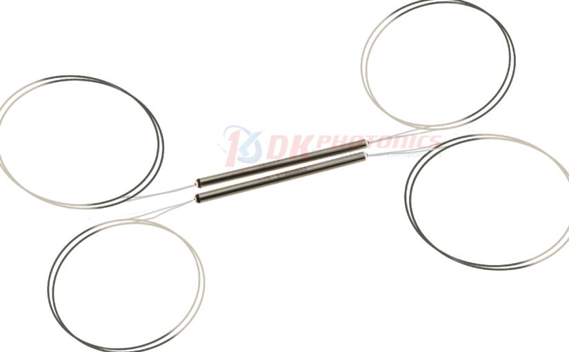
Most Splitters available in 900µm loose tube and 250µm bare fiber. 1×2 and 2×2 couplers come standard with a protective metal sleeve to cover the split. Higher output counts are built with a box to protect the splitting components.

Testing a coupler or splitter (both names are used for the same device) or other passive fiber optic devices like switches is little different from testing a patchcord or cable plant using the two industry standard tests, OFSTP-14 for double-ended loss (connectors on both ends) or FOTP-171 for single-ended testing.

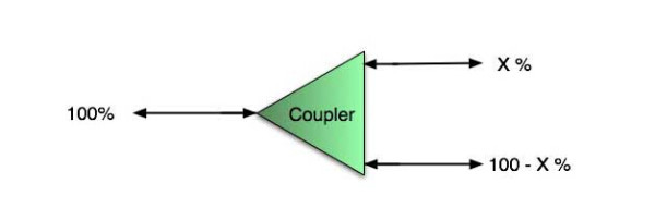
First we should define what these passive devices are. An optical coupler is a passive device that can split or combine signals in optical fibers. They are named by the number of inputs and outputs, so a splitter with one input and 2 outputs is a 1×2 fiber splitter, and a PON splitter with one input and 32 outputs is 1×32 splitter. Some PON splitters have two inputs so it would be a 2X32. Here is a table of typical losses for splitters.

Splitter-Ratio

Important Note! Mode Conditioning can be very important to testing couplers. Some of the ways they are manufactured make them very sensitive to mode conditioning, especially multimode but even singlemode couplers. Singlemode couplers should always be tested with a small loop in the launch cable (tied down so it does not change and set the 0dB reference with the loop.) Multimode couplers should be mode conditioned by a mandrel wrap or similar to ensure consistency.

Let’s start with the simplest type. Shown below is a simple 1X2 splitter with one input and two outputs. Basically, in one direction it splits the signal into 2 parts to couple to two fibers. If the split is equal, each fiber will carry a signal that is 3dB less than the input (3dB being a factor of two) plus some excess loss in the coupler and perhaps the connectors on the splitter module. Going the other direction, signals in either fiber will be combined into the one fiber on the other side. The loss is this direction is a function of how the coupler is made. Some couplers are made by twisting two fibers together and fusing them in high heat, so the coupler is really a 2X2 coupler in which case the loss is the same (3dB plus excess loss) in either direction. Some splitters use optical integrated components, so they can be true splitters and the loss in each direction may different.
optical coupler

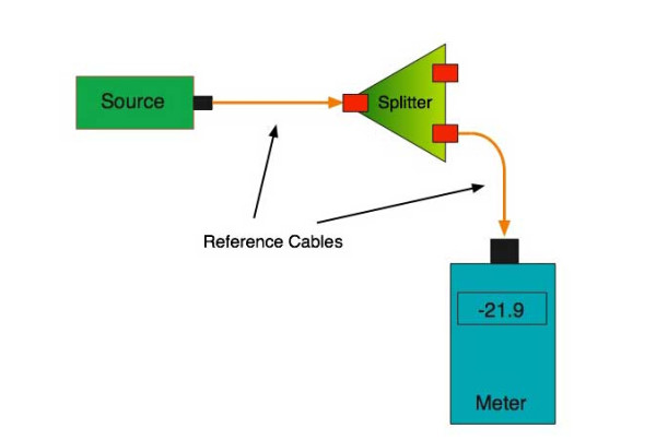
So for this simple 1X2 splitter, how do we test it? Simply follow the same directions for a double-ended loss test. Attach a launch reference cable to the test source of the proper wavelength (some splitters are wavelength dependent), calibrate the output of the launch cable with the meter to set the 0dB reference, attach to the source launch to the splitter, attach a receive launch cable to the output and the meter and measure loss. What you are measuring is the loss of the splitter due to the split ratio, excess loss from the manufacturing process used to make the splitter and the input and output connectors. So the loss you measure is the loss you can expect when you plug the splitter into a cable plant.

To test the loss to the second port, simply move the receive cable to the other port and read the loss from the meter. This same method works with typical PON splitters that are 1 input and 32 outputs. Set the source up on the input and use the meter and reference cable to test each output port in turn.

What about the other direction from all the output ports? (In PON terms, we call that upstream and the other way from the 1 to 32 ports direction downstream.) Simply reverse the direction of the test. If you are tesing a 1X2 splitter, there is just one other port to test, but with a 1X32, you have to move the source 32 times and record the results on the meter.
fiber-splitter

What about multiple input and outputs, for example a 2X2 coupler? You would need to test from one input port to the two outputs, then from the other input port to each of the two outputs. This involves a lot of data sometimes but it needs to be tested.

There are other tests that can be performed, including wavelength variations (test at several wavelengths), variations among outputs (compare outputs) and even crosstalk (put a signal on one output and look for signal on other outputs.)

Once installed, the splitter simply becomes one source of loss in the cable plant and is tested as part of that cable plant loss for insertion loss testing. Testing splitters with an OTDR is not the same in each direction.

Other Passive Devices

There are other passive devices that require testing, but the test methods are similar.

Fiber optic switches are devices that can switch an input to one of several outputs under electronic control. Test as you would the splitter as shown above. Switches may be designed for use in only one direction, so check the device specifications to ensure you test in the proper direction. Switches may also need testing for consistency after multiple switch cycles and crosstalk.

Attenuators are used to reduce signal levels at the receiver to prevent overloading the receiver. There is a page on using attenuators that you should read. If you need to test an attenuator alone, not part of a system, use the test for splitters above by using the attenuator to connect the launch and receive cables to see if the loss is as expected.

Wavelength-division multiplexers can be tricky to test because they require sources at a precise wavelenth and spectral width, but otherwise the test procedures are similar to other passive components.

Fiber optic couplers or splitters are available in a wide range of styles and sizes to split or combine light with minimal loss. All couplers are manufactured using a very simple proprietary process that produces reliable, low-cost devices. They are physically rugged and insensitive to operating temperatures. Couplers can be fabricated in custom fiber lengths and/or with terminations of any type.

DK Photonicswww.dkphotonics.com  specializes in designing and manufacturing of high quality optical passive components mainly for telecommunication, fiber sensor and fiber laser applications,such as PLC Splitter, WDM, FWDM, CWDM, DWDM, OADM,Optical Circulator, Isolator, PM Circulator, PM Isolator, Fused Coupler, Fused WDM, Collimator and Polarization Maintaining Components, Pump Combiner, High power isolator, Patch Cord and all kinds of connectors.
Optical Filters: Filter stacks transmit wide-angle incident light without shifting wavelength(2)

To avoid the problem of color change versus incidence angle in an optical system, thin-film-coated filter elements can be replaced by a filter consisting of a stack of different filter glasses.

JASON KECK

Wide-angle filter stack apps

There is a multitude of applications for this type of filter. In the field of digital imaging, colorimeters-which take wideband spectral energy readings-are used to profile and calibrate display devices, verifying that pixel color and intensity at the edge of a display matches the performance of pixels in the center of the display.

In astronomy, biomedical or fluorescence imaging, and mineralogy, hyperspectral imaging has many important applications. It is essential that the incident light undergo as little iridescence as possible. Also, when precision imaging instruments are expensively launched into orbit, the filters must be robust enough to withstand extreme environmental operating conditions.

In agriculture, the color of crops or food products reveals vital information. The use of Earth-observing satellites to measure the “vegetation index” of crops (a measurement of green hue) is nothing new, but the affordability of aerial drones has brought new possibilities. A drone can be programmed with GPS data to fly on a fixed pattern over a designated crop area and take wide-angle images at regular intervals, building up a picture of the vegetation index of crops. If the images used in such applications provide accurate spectral data that is as free as possible from iridescent distortion, it can give farmers precise control over fertilizer application rates and greatly improve efficiency and productivity. This is a considerable cost saving over low-resolution, narrowband satellite imagery and conventional aerial photography using manned aircraft.

Design hurdles

There are three complicating factors in the design of such filter stacks. The first is the limited choice in filter glass, limited not only by manufacturer availability but also by physics. Filter glass with an ideal edge cut-on or cut-off wavelength for an application is not always easy to find, or may be impossible to precisely manufacture. Where it is available, the designer is then limited by what the manufacturer can deliver in a reasonable time, as melts may be scheduled as infrequently as once every several years, depending on demand.

The second factor is that, while the perfect filter glass for a particular application may not exist, there are hundreds of other glass types from numerous vendors that can be combined to achieve a close approximation of the requirement.

The third complicating factor is that the design of ColorLock filters is a massively multidimensional, nonsmooth optimization challenge. Physical manufacturing requirements restrict the thickness of all combined individual layers to not exceed the overall thickness requirement of the resulting optical component, further putting restrictions on the selection of specific CWDM filter glass types.

Reynard streamlined this complex design process by developing in-house software into which all of the system requirements are fed. The software produces a manufacturable design for a filter in which the necessary materials are combined at the correct thickness in each layer. The design is then manufactured and validated for performance.

About DK Photonics

DK Photonics – www.dkphotonics.com  specializes in designing and manufacturing of high quality optical passive components such as 8CH CWDM Module,100GHz 8CH DWDM,200GHz DWDM,Mini-size CWDM,compact CWDM,Athermal AWG DWDM Module,100GHz AWG,Thermal AWG DWDM Module,1310/1490/1550nm FWDM, PLC Splitter, Optical Circulator,Optical Isolator,Fused Coupler,Mini Size Fused WDM.

Optical Filters: Filter stacks transmit wide-angle incident light without shifting wavelength(1)

To avoid the problem of color change versus incidence angle in an optical system, thin-film-coated filter elements can be replaced by a filter consisting of a stack of different filter glasses.

JASON KECK

Wide-angle imaging systems have to overcome numerous problems. Distortion of the shape of objects in the scene is the predominant issue, recognizable as the “fish-eye lens” look that is often corrected in software. However, lens distortion is not the only problem.

Iridescence, or the change in transmitted or reflected color of light viewed from different angles, is a phenomenon that can be found both in nature and in artificial light-detecting systems with precise color requirements, where it can cause many problems.

Wide-angle color-sensing applications commonly require that a CWDM wavelength must be detectable regardless of the incident angle. Iridescence through a thin-film-coated optical element can cause problems in this situation by distorting the spectral transmission of light coming from peripheral objects.

Maximizing light transmission in a thin-film WDM coating’s passband while blocking out-of-band light is a requirement for coated optical components such as dielectric filters; however, the wavelength’s transition commonly only remains steady within relatively narrow cone angles. Beyond angles of 5°, such filters are susceptible to iridescence, observable as a change of color, or “blueshift.” As the angle of light entering the filter increases, the light propagates through more of each thin-film stack layer, altering the apparent overall thickness of the optical-filter stack and affecting the performance of the original intended design. This can make such filters unsuitable for wide-angle imaging applications with bright illumination and where higher standards of consistency are required of the wavelength of all incident light.

One of the more convoluted wide-angle imaging solutions is the use of a cluster of cameras or a polycamera, pointing in various directions like the compound eye of an insect; the resulting multiple pictures are then assembled into one image in software. Although the light entering each camera thus fills only a narrow cone angle, the complexity and resultant high expense of such a system is obvious.

Engineers at Reynard have addressed this problem in a single optical device with a system in which two or more layers of filter glass are combined into a stacked configuration. These ColorLock filter stacks eliminate the wavelength shift as incident angle increases and are customized to meet specific system needs.

Software is used to determine the exact composition and thickness of the layers in these filters; the software determines a merit function that best estimates the filter requirements and allows filter stacks to be designed for band pass, short-wave pass, long-wave pass, or user-specified functions. Incident angles can be as high as 50° without any shift in the transmitted wavelength, while more traditional coated filters with the same conditions would see a significant shift toward shorter wavelengths.


About DK Photonics

DK Photonics – www.dkphotonics.com  specializes in designing and manufacturing of high quality optical passive components such as 8CH CWDM Module,100GHz 8CH DWDM,200GHz DWDM,Mini-size CWDM,compact CWDM,Athermal AWG DWDM Module,100GHz AWG,Thermal AWG DWDM Module,1310/1490/1550nm FWDM, PLC Splitter, Optical Circulator,Optical Isolator,Fused Coupler,Mini Size Fused WDM.

Fiber Optics Sensors Provide Early Warning for Landslides-DK Photonics

CASERTA, Italy, Sept. 29, 2014 — Fiber optic sensors could warn people of imminent landslides, potentially saving lives and reducing destruction.

A team at the Second University of Naples is developing sensor technology that could detect and monitor both large landslides and slow slope movements. The researchers hope to mitigate the effects of these major natural disasters, similar to the way hurricane tracking can prompt coastal evacuations.

Optical fiber sensors embedded in shallow trenches within slopes would detect small shifts in the soil, the researchers said. Landslides are always preceded by various types of pre-failure strains, they said.

While the magnitude of pre-failure strains depends on the rock or soil involved — ranging from fractured rock debris and pyroclastic flows to fine-grained soils — they are measurable. Electrical sensors have long been used for monitoring landslides, but that type of sensor can be easily damaged, the researchers said. Optical fiber is more robust, economical and sensitive.

“Distributed optical fiber sensors can act as a ‘nervous system’ of slopes by measuring the tensile strain of the soil they’re embedded within,” said professor Dr. Luigi Zeni.

The researchers are also combining several types of optical fiber sensors into a plastic tube that twists and moves under the forces of the pre-failure strains. This will allow them to monitor the movement and bending of the optical fiber remotely to determine if a landslide is imminent.

The use of fiber optic sensors “allows us to overcome some limitations of traditional inclinometers, because fiber-based ones have no moving parts and can withstand larger soil deformations,” Zeni said.

He added that such sensors can be used to cover several square kilometers and monitored continuously to pinpoint critical zones.

The team will present their research at Frontiers in Optics in Tucson, Ariz., next month.


DK Photonicswww.dkphotonics.com  specializes in designing and manufacturing of high quality optical passive components mainly for telecommunication, fiber sensor and fiber laser applications,such as PLC Splitter, WDM, FWDM, CWDM, DWDM, OADM,Optical Circulator, Isolator, PM Circulator, PM Isolator, Fused Coupler, Fused WDM, Collimator, Optical Switch and Polarization Maintaining Components, Pump Combiner, High power isolator, Patch Cord and all kinds of connectors.
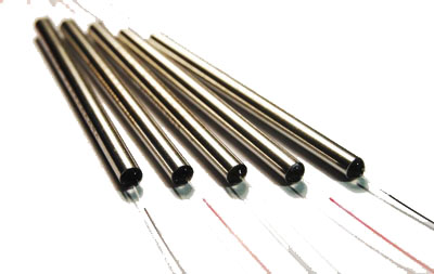
Fiber Optic Connector Market Forecast-DK Photonics

According to ElectroniCast, multifiber / multichannel fiber optic connectors are set for explosive growth, led by MXC™ fiber connectors with triple-digit increases through 2018…

Aptos, CA (USA) – September 22, 2014 —ElectroniCast Consultants, a leading market & technology forecast consultancy addressing the fiber optics communications industry, today announced the release of their annual market forecast and analysis of the use offiber optic connectors and mechanical splices in communication applications.

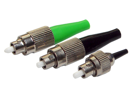
FC fiber optic connector

According to ElectroniCast, the worldwide fiber optic connector/mechanical splice consumption value reached $2.63 billion in 2013.  Multimode fiber optic connectors led the consumption value in 2013 with a 64 percent market share.  The use of multimode fiber optic connectors is forecast to increase at a rate of 14 percent per year, from $1.68 billion in 2013 to $3.24 billion in 2018.

“The multimode LC small form factor connector is forecast to maintain the leadership position in relative market share throughout the forecast period, as well as increasing at an average annual rate of 20 percent,” said Stephen Montgomery, Director of the Fiber Optic Component group at ElectroniCast.

The fastest annual growth is set to come from the use of multifiber/multichannel fiber optic connectors are set for explosive growth, led by MXC™ fiber connectors with triple-digit increases through 2018.  The newly-release connector design enables more fibers (up to 64 fibers at 25G) to be accommodated in fast-paced server/storage data center and other applications.  Both the single-mode and the multimode MXC fiber optic connectors are forecast to reach strong values by 2018.

Other new fiber optic connector designs, besides the MXC connector, are planned for deployment to address the high-density/high-speed data speeds of 25Gbps or greater in the next couple of years.

“Field-installable connectors for indoor and outdoor use are increasing in demand and thus are making a big-splash in the overall connector product lines of several competitors.  Fiber optic connector-types, such as SC, ST, LC, FC and even the MPO and other possibilities are finding their way to the marketplace.  Both mechanical-splice and fusion-splice technologies are meeting the requirements in the field-installable fiber optic product availability,” Montgomery added.

The global fiber optic connector/mechanical splice consumption is driven by a dramatic increase in bandwidth demand beyond the limits of copper.  As optical fiber use migrates closer and closer to the end user, where cable lengths are shorter with higher fiber counts, the requirements for jointing fibers becomes more critical. Splicing and connecting, play a significant role in a network’s cost and performance.

There are over 140 vendors competing for the global fiber optic connector/ mechanical splice market, which ElectroniCast tracks in a product matrix showing participation in the following: connectors, cable assemblies, optical backplanes, and fiber optic installation apparatus; however, is dominated by a few companies that have a broad base in various interconnect products.

DK Photonicswww.dkphotonics.com specializes in designing and manufacturing of high quality optical passive components mainly for telecommunication, fiber sensor and fiber laser applications,such as WDM, FWDM, CWDM, DWDM, OADM,Optical Circulator, Isolator, PM Circulator, PM Isolator, Fused Coupler, Fused WDM, Collimator, Optical Switch and Polarization Maintaining Components, Pump Combiner, High power isolator, Patch Cord and all kinds of connectors.

Differences Between FBT Coupler and PLC splitters

Optical networks require signal being splitted somewhere in design to serve for multiple customers. Splitter technology has made a huge step forward in the past few years by introducing PLC (Planar Lightwave Circuit) splitter. It has proven itself as a higher reliable type of device compared to the traditional FBT (Fused Biconical Taper) splitter. While being similar in size and outer appearance, both types of splitters provide data and video access for business and private customers. However, internally the technologies behind these types vary, thus giving  service providers a possibility to choose a more appropriate solution.

FBT splitter is made out of materials that are easily available, for example steel, fiber, hot dorm and others. All of these materials are low-price, which determines the low cost of the device itself. The technology of the device manufacturing is relatively simple, which has the impact on its price as well. In scenario where multiple splits are needed, the size of the device may become an issue. It is important to keep in mind that splitters are being deployed in the fields either in cabinets or in strand mountings, so the size of device plays a critical role. FBT splitters only support three wavelengths (850/1310/1550 nm) which makes these devices unable to operate on other wavelengths. Inability of adjusting wavelengths makes FBT splitters less customizable for different purposes. Moreover, the devices are to a high extent temperature sensitive, providing a stable working range of -5 to 75 C. In certain areas, such as Scandinavian countries this temperature restrictions may be crucial. The signal processed by FBT splitters cannot be splitted evenly due to lack of management of the signals

PLC splitter manufacturing technology is more complex. It uses semiconductor technology (lithography, etching, developer technology) production, hence it is more difficult to manufacture. Therefore, the price of the device is higher. However, there is a number of advantages the device possesses. The size of the device is compact, compared to FBT splitters, making it suitable for density applications. PLC splitter operates at wider temperature range (-40 to 85 C), allowing its deploying in the areas of extreme climate. The split ratio goes up to 64, providing a high reliability. Furthermore, the signal can be split equally due to technology implemented. A range of wavelengths (1260 – 1650 nm) is provided, so the wavelengths are adjustable. Critical points of the device that might fail are input and output, so the general risk of failure is low.

Differences Between FBT and PLC splitters

 Table 1. FBT and PLC splitter feature comparison

DK Photonicswww.dkphotonics.com  specializes in designing and manufacturing of high quality optical passive components mainly for telecommunication, fiber sensor and fiber laser applications,such as PLC Splitter, WDM, FWDM, CWDM, DWDM, OADM,Optical Circulator, Isolator, PM Circulator, PM Isolator, Fused Coupler, Fused WDM, Collimator, Optical Switch and Polarization Maintaining Components, Pump Combiner, High power isolator, Patch Cord and all kinds of connectors.

Market Forecast–MPO Connectors in 40/100GbE – DK Photonics

MPO fiber optic connectors used in North American 40/100GbE communication links are forecast to increase at a rate of 49.8% per year through 2018…

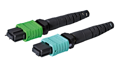
MPO

Aptos, CA (USA) – August 20, 2014 —ElectroniCast Consultants, a leading market & technology forecast consultancy addressing the fiber optics communications industry, today announced the release of their market forecast and analysis of the use of MPO fiber optic connectors in 40 gigabit Ethernet (GbE) and 100GbE Standard communication network links.  MPO is the industry acronym for “multi-fiber push on.”

“Applications such as video, virtualization, cloud computing, switching/routing and convergence are driving the need for bandwidth expansion in data centers, 4G/LTE (wireless) networks, and other deployments.  We continue on the path of gradually migrating from 1G to 10G to 40G and 100G and eventually beyond; and the MPO connector is a key component in 40/100GbE network links, ” said Stephen Montgomery, director of the fiber optics components group at ElectroniCast.

The use of MPO fiber optic connectors in North American 40GbE and 100GbE networks is expected to reach $28 million in 2014, an increase of 84% over last year (2013). The use of 40/100GbE MPO connectors in North American is forecast to increase at annual rate of 49.8% per year over the 2013-20189 timeframe covered in the ElectroniCast market forecast. Market forecast data in the market study refers to consumption (use) for a particular calendar year; therefore, this data is not cumulative data.

The market forecast is segment by the use of single-mode and multimode 12-fiber and 24-fiber MPO connectors, and further broken-out by the use of connectors in 40G and the connectors used in 100G.

According to the market study, the North American 40/100GbE MPO connector market expansion will be dominated by the 12-fiber multimode MPO connectors, increasing at an average annual growth rate of 48.5 percent during the forecast period.

DK Photonicswww.dkphotonics.com  specializes in designing and manufacturing of high quality optical passive components mainly for telecommunication, fiber sensor and fiber laser applications,such as PLC Splitter, WDM, FWDM, CWDM, DWDM, OADM,Optical Circulator, Isolator, PM Circulator, PM Isolator, Fused Coupler, Fused WDM, Collimator, Optical Switch and Polarization Maintaining Components, Pump Combiner, High power isolator, Patch Cord and all kinds of connectors.