Pump and signal combiner for bi-directional pumping of all-fiber lasers and amplifiers(10)

7. Signal feedthrough of the fiber combiner

Besides the pump power handling and the pump coupling efficiency of a fiber combiner, it is important for fiber laser and amplifier applications to maintain the optical properties of the signal light propagating through the fiber combiner. In particular, during the fabrication of the fiber component, externally induced mechanical stress and perhaps a marginal fraction of thermal diffusion of the core dopants [19] can result in a high signal insertion loss in conjunction with a degradation of the signal beam quality. This behavior was expected for large mode area DC fibers with a very low core refractive index (NA ~0.06), and therefore possible beam quality degradations of the signal feedthrough light was investigated (in Section 7.1).

The uninterrupted signal core in the fiber combiner provides the possibility of passing a signal beam through the combiner in forward and backward direction. However, in the case of a backward propagating signal, the pump diodes need sufficient protection against the signal. Thus, in Section 7.2 we investigate the signal to pump isolation of a 4 + 1×1 fiber combiner in a fiber amplifier setup.

7.1 Signal insertion loss and beam quality

In order to determine possible beam quality degradation and a signal insertion loss caused by the signal feedthrough of the combiner, the setup depicted in Fig. 14

fiber combiner

Fig. 14 Setup for beam quality measurements, TF: target fiber, PBS: polarization beam splitter.was used. A signal at a wavelength of 1064 nm was launched into the core of a 2.75 m long Ytterbium-doped DC fiber (Nufern YDF-25/250), which is specified with a signal core diameter of 25 µm (NA 0.06) and a pump core diameter of 250 µm (NA 0.46). Thus, the parameters of the passive TF of the combiner were matched to the active fiber. The coiling diameter of the active fiber was 12 cm to maintain near diffraction limited beam quality [20]. The transmitted signal had a power of about 200 mW and was propagating in reverse direction through the fiber combiner. The beam quality measurements were carried out with a Fabry-Perot ring-cavity. With this cavity it was possible to determine the power fraction in higher-order transversal cavity modes with respect to the Gaussian TEM00 mode by scanning the length of the ring-cavity over a free spectral range (FSR). A detailed description of the measuring setup can be found in Ref [21]. Due to the use of a polarization sensitive beam quality measurement, a half- and a quarter-wave retardation plate in conjunction with a polarization beam splitter (PBS) were used. The determined polarization extinction ratio was better than 17 dB after the propagation of the signal through the active fiber and the fiber combiner.

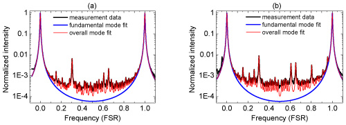
Before the fusion splice between the active fiber and the 4 + 1×1 combiner, the power in higher-order modes of the active fiber was determined. This measurement served as a reference beam quality for the active fiber. The mode scan in Fig. 15(a)

fiber combiner 2

Fig. 15 Normalized transmitted intensity through a premode cleaner as a function of the ring-cavity length in units of a free spectral range for (a) the reference beam and (b) the signal feedthrough beam of a 4 + 1×1 fiber combiner.

shows the logarithmic normalized intensity over a free spectral range for the reference beam with a power in higher-order modes of 3.1%. This results in a fundamental fiber mode power of at least 96.9% for the reference beam. For the signal feedthrough of the fiber combiner, a power in higher-order modes of only 5.1% was found (Fig. 15(b)).

Consequently, the signal feedthrough fiber (0.7 m long TF) only led to an increase in power in higher-order transversal modes of maximal 2%. Furthermore, it must be considered that additional power transfer to higher-order transversal modes can also be caused by the fusion splice between the active DC fiber and the TF. Hence, good preservation of the signal beam quality, in conjunction with the low signal insertion loss of less than 3%, provides an excellent high power fiber component for monolithic fiber laser and amplifier systems.

Work Theory of the Laser Cutting Machine(2)

Cutting methods of laser cutting machine

Vaporization cutting

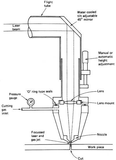
It means that vaporization is the main way to remove the processed material. In the process of vaporization cutting, workpiece surface is heated to vaporization temperature quickly by focused laser beams, forming High pressure steam and spraying outward at supersonic speeds. In the meantime, a hole is formed in the laser active area and laser beams reflex several times in the hole to increase the absorption of laser pump power combiner by material.

When high-pressure vapors spray outward, the melted materials are blown away in the kerf till the workpiece is finally cut. Vaporization cutting needs very high power density, which is eighth power of ten watt above per square centimeter. It is usually applied in low flash point materials and refractory materials.

Reaction Fusion Cutting

Reaction Fusion Cutting

When assistant airflow not only blows the melted materials from the kerf but also has thermal reaction with the workpiece, this is the so-called reaction fusion cutting. Gases that can have reaction with workpiece are oxygen or mixture gases containing oxygen. When the surface  temperature of workpiece reach to ignition temperature, strong combustion heat release occurs to improve the laser cutting ability.

Combustion heat release of low carbon steel and stainless steel is 60%. And it is about 90% for reactive metals like titanium.

Compared to vaporization cutting and general fusion cutting, reaction fusion cutting need less laser power density. However, reaction fusion cutting may effect the performance of worpiece since the combustion reaction can lead to chemical reaction on materials.

Fusion Cutting

When adding a assistant airflow system coaxial with laser to  blow the melted materials away from kerf, this kind of cutting is fusion cutting. In fusion fiber coupler cutting, workpiece needn’t to be heated to vaporization temperature so the required laser power density is reduced greatly.

Laser Scribing

It is mainly used in semiconductor materials, in which laser of high power density make a shallow groove in the semiconductor materials of the workpiece and then makes it crack through mechanistic or vibratory methods. The quality is valued by the surface fragments and size of heat affect area.

Cold Chipping

It is a new processing method, which is put forward along with ultraviolet band superpower excimer laser appeared in recent years. The basic theory is that energy of ultraviolet photons is similar to binding energy of many organic materials; this high-energy photons are used to impact bond organic materials thus make it crack, achieving purpose of cutting. This new technology has promising application future, especially in electron industry.

Thermal Stress Cutting

Mechanism of thermal stress cutting is that laser beams heat an area of fragile material to produce evident temperature gradient. The high surface temperature makes expansion and inner lower temperature hinders expansion, forming pulling stress in the surface and radial crushing stress inside. When the two stresses exceed fracture limit strength of the workpiece, crackle appears. And then the workpiece is broken along the normal direction of the crack. It is suitable for glasses and ceramics.

Conclusion: laser cutting machine is a cutting technology of melting and gasifying surface material through focused energy generated by the use of laser specialties and focused lens. It features good cutting quality, high speed, various cutting material and high efficiency.

About DK Photonics

DK Photonics – www.dkphotonics.com  specializes in designing and manufacturing of high quality optical passive components mainly for fiber laser applications such as 1064nm high power isolator, Cladding Power Stripper, Multimode High Power Isolator, pump combiner,1064nm Band-pass Filter,(6+1)X1 Pump and Signal Combiner, PM Circulator, PM Isolator, optical Coupler. More information, please contact us.


Work Theory of the Laser Cutting Machine(1)

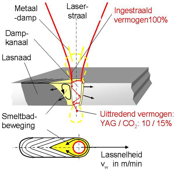
Laser has been applied in teaching, military as well as industrial production. Laser cutting machine is one of the applications. It can be used in both metal and non-metal cutting, Melting surface material by laser beam. This article will discuss the work theory of laser cutting machine.

Introduction on the work theory of laser cutting machine

Introduction on the work theory of laser cutting machine.

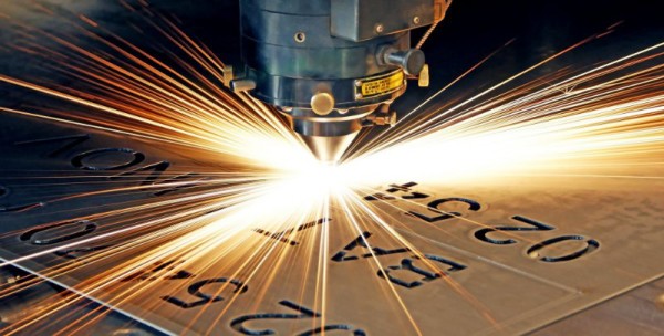
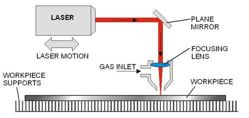
Laser cutting machine adopts the energy released on the time when laser beam irradiate metal surface. The metal is melt by laser and sinter is blow away by gas. Because laser power is highly focused, only a very little heat effects the other part of metal plate and causes a little or no deformation. Laser can cut any complex shape precisely, which needs no further processing.

Laser source is generally CO2 laser beam high power isolator with operating power of 500~5000W. The power is even lower than that of many household electric heater, and because of lenses and reflectors, laser beams are focused in a very small bit of area. Highly focused energy heat the area quickly and makes the metal plate melted.

Laser cutting machine can cut stainless steal of thickness less than 16mm; when adding oxygen in laser beam, the cutting thickness is 8~10mm but it will generate a thin oxidation film in the cut surface. The maximum thickness is 16mm which leads to larger cutting deviation on the size of components.

Since the advent of laser, numerous laser products have been developed, such as laser printer, laser cosmetic instrument, laser marker, laser cutting machine etc. Due to its late start in China, the laser technology in China is greatly behind the developed countries. Although Chinese manufacturers can produce plenty of laser products, some key parts such as laser tube, driving motor, galvanometer and focus lens are imported products. This leads to an increase on cost thus an increase on consumer’s payment.

In recent years, domestic research and production of  laser products become closer to advanced overseas products with the progress of laser technology in China. Some aspects are even superior to products abroad, which has a leading role in market because of the  advantages of price. Overseas products have absolute predominance in precision machining for its quality on stability and endurance.

Work theory of laser cutting machine

Work theory of laser cutting machine

Laser tube is the core part of laser cutting machine. So, below is an introduction of the most popular laser tube. CO2 laser tube.

Laser tube is composed of hard glasses, so it is fragile. It adopts layer of sleeve construction with discharge tube in the most inside layer. However, the diameter of discharge tube is thicker than laser tube, diffraction between the thickness of discharge tube and the size of flare is in direct ratio; the length of tube is in proportion to output power of discharge tube.  Laser tube generates a large quantity of heat in the operation of laser cutting machine, which influences the normal work. So cold water machine is needed to cool laser tube, ensuring constant temperature for successful running.

Cutting features of laser cutting machine

Advantages of laser cutting:

One — high efficiency

Laser cutting machine is always connected to several numerically-controlled rotary tables to achieve numerical controlled cutting. It only needs to change the NC program to adjust to components of different shapes, which can make 2D cutting as well as 3D cutting.

Two — high speed

When cutting low carbon steel sheets of 2mm thickness, the speed of 1200W laser cutting is 600cmmin; when it is 5mm thick polypropylene resin plate, the cutting speed is 1200cmmin. The material needs no clamping fix in laser cutting process.

Three — high quality cutting

Laser cutting features thin kerf. The two sides of kerf are parallel and the kerf is vertical to the surface. The cutting precision can reach to ±0.05mm. The cutting surface is clean and nice, with roughness of tens of microns. The cut components can even come into use directly without further machining. After laser cutting, the heat effected area is very small and material near to kerf has not been affected, making little deformation, high cutting precicion and perfect geometrical shape

Four — non-contact cutting

Laser cutting is non-contact cutting, which means no tool wear problem. When processing different shapes, there is no need to change tools, the only way is to alter the output parameter of laser. The whole laser cutting process features low noise, little vibration and little pollution.

Five — various cutting material

Compared to oxyacetylene cutting and plasma cutting, laser cutting can be applied on more materials, including metal and non-metal, metal matrix and non-metallic matrix composite, leather, wood as well as fibers.

About DK Photonics

DK Photonics – www.dkphotonics.com  specializes in designing and manufacturing of high quality optical passive components mainly for fiber laser applications such as 1064nm high power isolator, Cladding Power Stripper, Multimode High Power Isolator, pump signal combiner,1064nm Band-pass Filter,(6+1)X1 Pump and Signal Combiner, PM Circulator, PM Isolator, optical Coupler. More information, please contact us.

Pump and signal combiner for bi-directional pumping of all-fiber lasers and amplifiers(9)

6. Demonstration of 440 W pump power handling

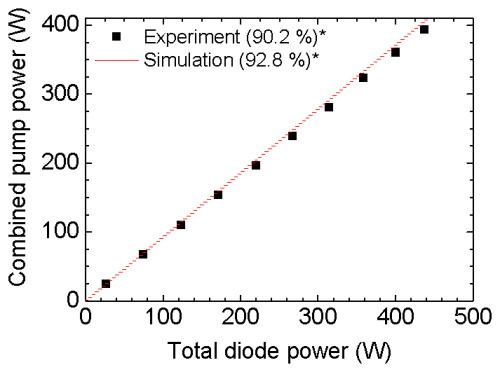
After detailed theoretical and experimental characterization of fiber pump combiners with multiple pump ports, a pump power handling performance test was conducted. For these investigations each pump port of a 4 + 1×1 combiner was connected to a fiber coupled pump diode (nLight Pearl) with an output power of ~110 W at a wavelength of 976 nm. The PFF and the delivery fiber of the pump diode had a core diameter of 105 µm with a NA of 0.22. At each fiber output end of the IF, a pump light stripper was applied to avoid the Fresnel reflection of the TP, and therefore the TP was not measured. Up to the maximum total pump diode power of 440 W, a coupling efficiency of 90.2% was experimentally determined (Fig. 13

fiber pump combiners

Fig. 13 Combined pump power for a 4+1×1 high power fiber combiner, * ratio of coupled power to total diode power in percent.

). In the simulations a slightly higher coupling efficiency of 92.8% was obtained. The difference of 2.6% in simulated and measured pump light coupling must be distributed among TP, PAA and PCT, with simulated values of 3.0, 1.4 and 1.7%, respectively. It can be assumed that the PAA-fraction is higher than 1.4%, since the fibers of the combiner are contaminated with dust particles in spite of intensive cleaning. If we assume for each individual loss mechanism an error of 1% related to the total diode power then PCT was 7.5 W ± 4.4 W, i.e. the coating of the TF and the pump power stripper had to handle this fraction of power.

About DK Photonics

DK Photonics – www.dkphotonics.com  specializes in designing and manufacturing of high qualityoptical passive components mainly for fiber laser applications such as 1064nm high power isolator,Cladding Power Stripper, High Power Isolator,pump combiner,1064nm Band-pass Filter,(6+1)X1 Pump and Signal Combiner,PM Circulator,PM Isolator,optical Coupler.More information,please contact us.

Fiber Laser Welding: Some Traits and Applications(2)

Technological parameter of laser welding:

(1) Power density

Power density is one of the key parameters in laser processing. When the power density is relatively high, the surface would be heated to boiling point in microseconds, thus generate mass vaporization. As a result, high power density is good for material removal processing such as punching, cutting and carving. When the power density is relatively low, it would take some microseconds to meet the boiling point, the bottom can reach the melting point before vaporization occurs, thus a good melt welding is successfully formed. So the power density ranges from 104~106W/cm2 in conductive laser welding.

(2) Laser pulse shape

Laser pulse shape is an important question in laser welding, especially for foil welding. When high strength laser beam reaches the material surface, 60~98% of the laser energy will be lost by reflection and the reflectivity is changeable by the temperature of the material surface. The reflectivity of metal can vary greatly in a laser pulse period.

(3) Laser pulse width

Laser pulse width is an important parameter to distinguish material removal and material melting; it is also a key parameter to decide the cost and volume of processing equipment.

(4) Influence of defocusing amount on weld quality

There are two ways of defocus: positive defocus and negative defocus. It is positive defocus when focal plane is above the workpieces, vise versa. According to geometry optical theory, when positive and negative defocusing plane equals to welding plane, the power densities are almost the same in the corresponding panels, but the actual laser pools have different forms. It can achieve larger depth of fusion when it is negative defocus.

Application field of laser welding

Laser welding machine has wide application in manufacturing industry, powder metallurgy field, automobile industry, electronics and some other fields.

fiber laser 3

Source : demarlaser

Application of laser welding in automobile industry

Volkswagen AG has adopted laser welding in car roof of brands like AudiA6, GolfA4 and Passat. BMW and GM have used laser welding in top of the car frame while Mercedes-Benz has applied laser welding in drive disk assembly. Except for laser welding, other laser technologies have be applied as well. Companies like Volkswagen GM, Benz and Nissan have used laser to cut covering parts while FIAT and Toyota have adopted laser for coating engine exhaust valve; Volkswagen has used laser for surface hardening on engine camshaft. Domestic vehicle models like Passat, Polo, Touran, Audi, Dongfeng Peugeot and Focus have adopted laser welding technology.

Independent automobile brands like Brilliance, Chery and Geely have adopted laser welding as well.

Improvement and development of new laser welding technology

Laser welding technology is continuously developing along with the progress of the time. The following three technologies can help expanding laser’s application scop and enhancing the automatic control level of laser welding.

  1. filler wire laser welding

Laser welding generally doesn’t fill wires but has high requirement on assembling clearance, which is hard to be guaranteed thus limits the application scope. Filler wire laser welding method has lower requirement on assembling clearance. For example, if the aluminum alloy plate is of 2 mm’s thickness, the clearance must be zero for a good shaping. When adopting φ1.6mm welding wire as filler metal, it can form good shape even the clearance is 1.0 mm. Besides, filler wire can be used for adjusting chemical components and multi-layer welding on thick board.

  1. Beam rotation laser welding

By the adoption of laser beam rotation laser welding methods, demands on welding assembly and beam centering are reduced greatly.

  1. On-line detection and control of laser welding quality

It is becoming a hot researching topic on detecting laser welding process by using plasma such as light, sound and electric charge; some researches have achieved closed-loop control.

DK Photonics – www.dkphotonics.com  specializes in designing and manufacturing of high quality optical passive components mainly for fiber laser applications such as 1064nm high power isolator, Cladding Power Stripper, Multimode High Power Isolator, pump combiner,1064nm Band-pass Filter,(6+1)X1 Pump and Signal Combiner, PM Circulator, PM Isolator, optical Coupler. More information, please contact us.

Polarization Dependent Isolator vs Polarization Independent Isolator

Connectors and other types of optical devices on the output of the transmitter may cause reflection, absorption, or scattering of the optical signal. These effects on the light beam may cause light energy to be reflected back at the source and interfere with source operation. In order to reduce the effects of the interference, an optical isolator is usually used. Optical isolator allows a beam of light to stream through a single one way direction. At the same time, it prevents the light from going back in the opposite direction. According to the polarization characteristics, optical isolators can be divided into two types, including polarization dependent isolator and polarization independent isolator. The polarizer-based module makes a polarization dependent isolator, and the birefringent crystal-based structure makes a polarization independent isolator. You may be very confused about them as you find that there is only a little difference via their names. So, what are they and what are the differences between them? This paper will give you the answer.

Polarization Dependent Isolator

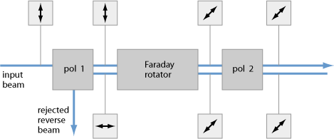
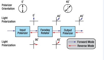
The polarization dependent isolator consists of three parts, an input polarizer , a Faraday rotator, and an output polarizer. Light traveling in the forward direction becomes polarized vertically by the input polarizer. The Faraday rotator will rotate the polarization by 45°. The analyser then enables the light to be transmitted through the isolator.

Polarization-Dependent-Isolator

Light traveling in the backward direction becomes polarized at 45° by the analyser. The Faraday rotator will again rotate the polarization by 45°. This means the light is polarized horizontally. Since the polarizer is vertically aligned, the light will be extinguished.

The picture shows us a Faraday rotator with an input polarizer, and an output analyser. For a polarization dependent isolator, the angle between the polarizer and the analyser, is set to 45°. The Faraday rotator is chosen to give a 45° rotation.

Because the polarization of the source is typically maintained by the system, polarization dependent isolator is widely used in free space optical systems.

Polarization Independent Isolator

The polarization independent isolator also consists of three parts, an input birefringent wedge, a Faraday rotator, and an output birefringent wedge. Light traveling in the forward direction is split by the input birefringent wedge into its vertical (0°) and horizontal (90°) components, called the ordinary ray (o-ray) and the extraordinary ray (e-ray) respectively. The Faraday rotator rotates both the o-ray and e-ray by 45°. This means the o-ray is now at 45°, and the e-ray is at −45°. The output birefringent wedge then recombines the two components.

Polarization-Independent-Isolator

Light traveling in the backward direction is separated into the o-ray at 45, and the e-ray at −45° by the birefringent wedge. The Faraday Rotator again rotates both the rays by 45°. Now the o-ray is at 90°, and the e-ray is at 0°. Instead of being focused by the second birefringent wedge, the rays diverge. The picture shows the propagation of light through a polarization independent isolator.

While polarization dependent isolator allows only the light polarized in a specific direction, polarization independent isolator transmit all polarized light. So it is usually widely used in optical fiber amplifier.

Comparison of Polarization Dependent Isolator and Polarization Independent Isolator

In fact, you have already understood these two types of isolators according to the contents above. We can see their similarities and differences through the comparison of their definition, working principle and applications. Both of them consist of three parts and have a same principle based on Faraday effect. However, to overcome the limitation of polarization dependent isolator, polarization independent isolator has been developed. Regardless of the polarization state of the input beam, the beam will propagate through the isolator to the output fiber and the reflected beam will be isolated from the optical source. If the extinction ratio is important, a polarization dependent isolator should be used with either polarization maintaining fibers or even regular single-mode fibers. If the system has no polarization dependence, a polarization independent isolator will be the obvious choice.

About DK Photonics

DK Photonics – www.dkphotonics.com  specializes in designing and manufacturing of high quality optical passive components mainly for fiber laser applications such as 1064nm high power isolator, Cladding Power Stripper, Multimode High Power Isolator, pump combiner,1064nm Band-pass Filter,(6+1)X1 Pump and Signal Combiner, PM Circulator, PM Isolator, optical Coupler. More information, please contact us.

Introduction of the Transients in Optical WDM Networks

A systems analysis continues to be completed to consider dynamical transient effects in the physical layer of an Optical WDM Network. The physical layer dynamics include effects on different time scales. Dynamics from the transmission signal impulses possess a scale of picoseconds. The timing recovery loops in the receivers be employed in the nanoseconds time scale. Optical packet switching in the future networks will have microsecond time scale. Growth and development of such optical networks is yet continuing. Most of the advanced development work in optical WDM networks is presently focused on circuit switching networks, where lightpath change events (for example wavelength add/drop or cross-connect configuration changes) happen on the time scale of seconds.

It is focused on the dynamics from the average transmission power associated with the gain dynamics in Optical Line Amplifiers (OLA). These dynamics may be triggered by the circuit switching events and have millisecond time scale primarily defined by the Amplified Spontaneous Emission (ASE) kinetics in Erbium-Doped Fiber Amplifiers (EDFAs). The transmission power dynamics will also be influenced by other active components of optical network, for example automatically tunable 100GHz DWDM, spectral power equalizers, or other light processing components. When it comes to these dynamics, a typical power of the lightpath transmission signal is recognized as. High bandwidth modulation from the signal, which actually consists of separate information carrying pulses, is mostly ignored.

14_nodes Ring WDMRing WDM networks implementing communication between two fixed points are very well established technology, in particular, for carrying SONET over the WDM. Such simple networks with fixed WDM lighpaths happen to be analyzed in many detail. Fairly detailed first principle models for transmission power dynamics exist for such networks. These models are implemented in industrial software allowing engineering design calculations and dynamical simulation of these networks. Such models could possibly have very high fidelity, but their setup, tuning (model parameter identification) and exhaustive simulations covering a variety of transmission regimes are potentially very labor intensive. Adding description of new network components to such model could need a major effort.

14_nodes Mesh WDMThe problems with detailed first principle models is going to be greatly exacerbated for future Mesh WDM networks. The near future core optical networks will be transparent to wavelength signals on a physical layer. In such network, each wavelength signal travels through the optical core between electronic IP routers around the optical network edge using the information contents unchanged. The signal power is attenuated in the passive network elements and boosted by the optical amplifiers. The lightpaths is going to be dynamically provisioned by Optical Cross-Connects (OXCs), routers, or switches independently on the underlying protocol for data transmission. Such network is basically a circuit switched network. It might experience complex transient processes of the average transmission power for every wavelength signal at the event of the lightpath add, drop, or re-routing. A mix of the signal propagation delay and channel cross-coupling might result in the transmission power disturbances propagating across the network in closed loops and causing stamina oscillations. Such oscillations were observed experimentally. Additionally, the transmission power and amplifier gain transients could be excited by changes in the average signal power because of the network traffic burstliness. If for some period of time the wavelength channel bandwidth is not fully utilized, this could result in a loss of the average power (average temporal density of the transmitted information pulses).

First circuit switched optical networks are already being designed and deployed. Fraxel treatments develops rapidly for metro area and long term networks. Engineering design of circuit switched networks is complicated because performance has to be guaranteed for all possible combinations of the lightpaths. Further, as such networks develop and grow, they potentially need to combine heterogenous equipment from a variety of vendors. A system integrator (e.g., DK Photonics) of such network might be different from subsystems or component manufacturer. This creates a necessity of developing adequate means of transmission power dynamics calculations which are suitable for the circuit switched network business. Ideally, these methods should be modular, independent on the network complexity, and use specifications on the component/subsystem level.

DK Photonics has technical approach to systems analysis that’s to linearize the nonlinear system around a fixed regime, describe the nonlinearity like a model uncertainty, and apply robust analysis that guarantees stability and gratifaction conditions within the presence of the uncertainty. For a user of the approach, there is no need to understand the derivation and system analysis technicalities. The obtained results are very simple and relate performance to basic specifications of the network components. These specifications are somewhat not the same as those widely used in the industry, but could be defined from simple experimentation using the components and subsystems. The obtained specification requirements may be used in growth and development of optical amplifiers, equalizers, optical attenuators, other transmission signal conditioning devices, OADM Modules, OXCs, and any other optical network devices and subsystems influencing the transmission power.

DK Photonics – www.dkphotonics.com  specializes in designing and manufacturing of high quality optical passive components mainly for telecommunication, fiber sensor and fiber laser applications,such as WDM, FWDM, CWDM, DWDM, OADM,Optical Circulator, Isolator, PM Circulator, PM Isolator, Fused Coupler, Fused WDM, Collimator, Optical Switch and Polarization Maintaining Components, Pump Combiner, High power isolator, Patch Cord and all kinds of connectors.

Large Mode Area Fibers

Optical fibers with relatively large mode areas and a single transverse mode or only a few modes.

For some applications, it is desirable to use optical fibers with a large mode area (LMA fibers) – often with single-mode guidance. Due to the reduced optical intensities, such fibers effectively have lower nonlinearities and a higher damage threshold, which makes them suitable for example for the Amplification of intense Pulses or single-frequency signals in Fiber amplifiers, or in case of passive fibers for delivery of such light. While standard single-mode fibers have an Effective Mode Area below 100 μm2, large mode area fibers reach values of hundreds or even thousands of μm2.

DK Photonics – www.dkphotonics.com  specializes in designing and manufacturing of high quality optical passive components mainly for fiber laser applications such as 1064nm high power isolator, Cladding Power Stripper, Multimode High Power Isolator, pump combiner,1064nm Band-pass Filter,(6+1)X1 Pump and Signal Combiner, PM Circulator, PM Isolator, optical Coupler. More information, please contact us.

Testing Fiber Optic Splitters Or Other Passive Devices

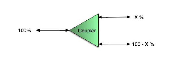
A fiber optic splitter is a device that splits the fiber optic light into several parts by a certain ratio. For example, when a beam of fiber optic light transmitted from a 1X4 equal ratio splitter, it will be divided into 4-fiber optic light by equal ratio that is each beam is 1/4 or 25% of the original source one. A Optical Splitter is different from WDM. WDM can divide the different wavelength fiber optic light into different channels. fiber optic splitter divide the light power and send it to different channels.

Most Splitters available in 900µm loose tube and 250µm bare fiber. 1×2 and 2×2 couplers come standard with a protective metal sleeve to cover the split. Higher output counts are built with a box to protect the splitting components.

Testing a coupler or splitter (both names are used for the same device) or other passive fiber optic devices like switches is little different from testing a patchcord or cable plant using the two industry standard tests, OFSTP-14 for double-ended loss (connectors on both ends) or FOTP-171 for single-ended testing.

First we should define what these passive devices are. An optical coupler is a passive device that can split or combine signals in optical fibers. They are named by the number of inputs and outputs, so a splitter with one input and 2 outputs is a 1×2 fiber splitter, and a PON splitter with one input and 32 outputs is 1×32 splitter. Some PON splitters have two inputs so it would be a 2X32. Here is a table of typical losses for splitters.

Splitter-Ratio

Important Note! Mode Conditioning can be very important to testing couplers. Some of the ways they are manufactured make them very sensitive to mode conditioning, especially multimode but even singlemode couplers. Singlemode couplers should always be tested with a small loop in the launch cable (tied down so it does not change and set the 0dB reference with the loop.) Multimode couplers should be mode conditioned by a mandrel wrap or similar to ensure consistency.

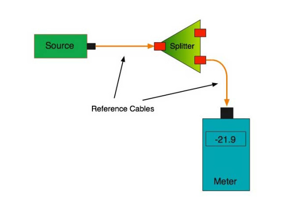
Let’s start with the simplest type. Shown below is a simple 1X2 splitter with one input and two outputs. Basically, in one direction it splits the signal into 2 parts to couple to two fibers. If the split is equal, each fiber will carry a signal that is 3dB less than the input (3dB being a factor of two) plus some excess loss in the coupler and perhaps the connectors on the splitter module. Going the other direction, signals in either fiber will be combined into the one fiber on the other side. The loss is this direction is a function of how the coupler is made. Some couplers are made by twisting two fibers together and fusing them in high heat, so the coupler is really a 2X2 coupler in which case the loss is the same (3dB plus excess loss) in either direction. Some splitters use optical integrated components, so they can be true splitters and the loss in each direction may different.

optical coupler

So for this simple 1X2 splitter, how do we test it? Simply follow the same directions for a double-ended loss test. Attach a launch reference cable to the test source of the proper wavelength (some splitters are wavelength dependent), calibrate the output of the launch cable with the meter to set the 0dB reference, attach to the source launch to the splitter, attach a receive launch cable to the output and the meter and measure loss. What you are measuring is the loss of the splitter due to the split ratio, excess loss from the manufacturing process used to make the splitter and the input and output connectors. So the loss you measure is the loss you can expect when you plug the splitter into a cable plant.

To test the loss to the second port, simply move the receive cable to the other port and read the loss from the meter. This same method works with typical PON splitters that are 1 input and 32 outputs. Set the source up on the input and use the meter and reference cable to test each output port in turn.

What about the other direction from all the output ports? (In PON terms, we call that upstream and the other way from the 1 to 32 ports direction downstream.) Simply reverse the direction of the test. If you are tesing a 1X2 splitter, there is just one other port to test, but with a 1X32, you have to move the source 32 times and record the results on the meter.

fiber-splitter

What about multiple input and outputs, for example a 2X2 coupler? You would need to test from one input port to the two outputs, then from the other input port to each of the two outputs. This involves a lot of data sometimes but it needs to be tested.

There are other tests that can be performed, including wavelength variations (test at several wavelengths), variations among outputs (compare outputs) and even crosstalk (put a signal on one output and look for signal on other outputs.)

Once installed, the splitter simply becomes one source of loss in the cable plant and is tested as part of that cable plant loss for insertion loss testing. Testing splitters with an OTDR is not the same in each direction.

Other Passive Devices

There are other passive devices that require testing, but the test methods are similar.

Fiber optic switches are devices that can switch an input to one of several outputs under electronic control. Test as you would the splitter as shown above. Switches may be designed for use in only one direction, so check the device specifications to ensure you test in the proper direction. Switches may also need testing for consistency after multiple switch cycles and crosstalk.

Attenuators are used to reduce signal levels at the receiver to prevent overloading the receiver. There is a page on using attenuators that you should read. If you need to test an attenuator alone, not part of a system, use the test for splitters above by using the attenuator to connect the launch and receive cables to see if the loss is as expected.

Wavelength-division multiplexers can be tricky to test because they require sources at a precise wavelenth and spectral width, but otherwise the test procedures are similar to other passive components.

Fiber optic couplers or splitters are available in a wide range of styles and sizes to split or combine light with minimal loss. All couplers are manufactured using a very simple proprietary process that produces reliable, low-cost devices. They are physically rugged and insensitive to operating temperatures. Couplers can be fabricated in custom fiber lengths and/or with terminations of any type.

DK Photonicswww.dkphotonics.com  specializes in designing and manufacturing of high quality optical passive components mainly for telecommunication, fiber sensor and fiber laser applications,such as PLC Splitter, WDM, FWDM, CWDM, DWDM, OADM,Optical Circulator, Isolator, PM Circulator, PM Isolator, Fused Coupler, Fused WDM, Collimator and Polarization Maintaining Components, Pump Combiner, High power isolator, Patch Cord and all kinds of connectors.

Pump and signal combiner for bi-directional pumping of all-fiber lasers and amplifiers(7)

Pump and signal combiner for bi-directional pumping of all-fiber lasers and amplifiers(7)

5. Simulations and results for a multi pump port configuration

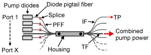
So far, the modeling results consider a TF with only a single pump port. However, for monolithic high power fiber laser and amplifier systems, it is often required to provide multiple pump ports due to the limited output power of available fiber coupled pump diodes and the efforts to develop laser systems with redundancy. Thus, in this section, we investigate the impact of multiple pump ports on the coupling efficiency and the loss mechanism. The setup of each pump combiner is identical to the description in Section 2 (see Fig. 1), but with several additional ports placed around the cladding of the TF, leading to a fiber bundle. A schematic of a fiber combiner with multiple pump ports is shown in Fig. 7

Pump and signal combiner for bi-directional pumping of all-fiber lasers and amplifiers(7)

Fig. 7 Fiber combiner with multiple pump ports, PFF: pump feeding fiber with a piece of coreless intermediate fiber (IF) as described in Fig. 1, TF: target fiber, TP: transmitted power.

5.1 Simulations of the pump coupling efficiency

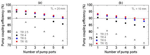
The experiments and simulations in Section 4 showed that for a pump combiner with a single pump port, a TL of 20 mm and a TR of 6 yields an excellent coupling efficiency in the range of 95%. In comparison, for a fiber band pass filter with multiple pump ports, the simulations for a TL of 20 mm (Fig. 8(a)

Pump and signal combiner for bi-directional pumping of all-fiber lasers and amplifiers(7)-2

Fig. 8 Simulated coupling efficiency for a pump combiner with up to 6 pump ports for (a) a TL of 20 mm and (b) a TL of 10 mm for a pump light input NA of 0.22.

) revealed that the pump coupling efficiency of the combined pump power depends on the number of pump ports and significantly on the choice of the TR. In the simulations the input pump light NA of the PFFs was 0.22. In general, it can be seen that the pump coupling efficiency decreases with each additional pump port. A lower TR yields a greater decrease of the pump coupling efficiency with each additional pump port than a higher TR. In the case of a TL of 20 mm and a TR of 2.5, the theoretically obtainable pump coupling efficiency of almost 90% decreases to 73%, if the number of pump ports increases from 1 to 6. However, as already mentioned, the increasing losses due to additional pump ports can be reduced with increasing TR. In Fig. 8(a) it can be clearly observed that for 6 pump ports and a TR of 6, a pump coupling efficiency of 90.2% can be achieved. For a TR higher than 6, it is not possible to achieve a significant improvement in pump coupling efficiency for multiple pump ports by increasing of the TR.

For a single pump port configuration it is already known that the pump coupling efficiency decreases with shorter TLs at constant TRs (Fig. 2(a)). However, for multiple pump ports a reduction of the TL leads to the advantage that the pump coupling efficiency of the combined pump power decreases less with each additional pump port, especially at lower TRs. The simulation results for a TL of 10 mm instead of a TL of 20 mm are presented in Fig. 8(b). A comparison of Fig. 8(a) and 8(b) shows: If the number of pump ports is increased from 1 to 6 at a TR of 2.5, the pump coupling efficiency experiences a decrease of 16.9 and 11.2% for a TL of 20 and 10 mm, respectively. Although the total power losses for a TL of 10 mm are higher than for a TL of 20 mm, the example reveals, that the decrease of the pump coupling efficiency due to additional pump ports can be reduced by using shorter TLs.

Besides having less available combined pump power, the additional pump power losses generated in comparison to a fiber combiner with a single pump port, corresponds to an enhanced risk of damaging the component due to additional thermal load. Hence, the loss mechanism for a fiber combiner with multiple pump ports needs to be investigated in more detail.

About DK Photonics

DK Photonics – www.dkphotonics.com  specializes in designing and manufacturing of high quality optical passive components mainly for fiber laser applications such as 1064nm high power isolator, Cladding Power Stripper, Multimode High Power Isolator, pump combiner,1064nm Band-pass Filter,(6+1)X1 Pump and Signal Combiner, PM Circulator, PM Isolator, optical Coupler. More information, please contact us.