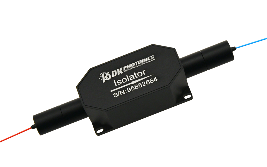
The 1064nm High Power In-line Optical Isolator is made of TGG crystal with excellent performance. They’re characterized with low insertion loss, high isolation, high power handling, high return loss, excellent environmental stability and reliability. Optical Isolators allow light to be transmitted in one direction only. They are most often used to prevent any reflected light from entering the source, thus preventing any feedback problems; it has been widely used in fiber laser system.
The 1064nm High Power In-line Optical Isolator is made of TGG crystal with excellent performance. They’re characterized with low insertion loss, high isolation, high power handling, high return loss, excellent environmental stability and reliability. Optical Isolators allow light to be transmitted in one direction only. They are most often used to prevent any reflected light from entering the source, thus preventing any feedback problems; it has been widely used in fiber laser system.
PM and non-PM types are available, fiber can be customized, with power conditions of CW or Pulse and Power Handling of 5W, 10W, 20W, 30W, 50W can be customized.
If you do not see a standard isolator that meets your needs, we welcome the opportunity to review your desired specification and quote a custom isolator. Requests for custom fiber pigtails, different wavelengths and handling power of operation or other specific needs will be readily addressed.
| PARAMETERS | UNIT | VALUES |
| Central Wavelength | nm | 1064 |
| Operating Wavelength Range | nm | ±10 |
| Typ. Peak Isolation | dB | 35 |
| Min. Isolation in Band (at 25℃) | dB | 28 |
| Typ. Insertion Loss | dB | 0.6 |
| Max. Insertion Loss (at 25℃) | dB | 1.0 |
| Max. PDL (for SM fiber) | dB | 0.15 |
| Min. Extinction Ratio (for PM fiber) | dB | 18(Type B), 20(Type F) |
| Min. Return Loss | dB | 45 |
| Max. Power Handling (CW) | IN | 10, 20, 30 |
| Max. Peak Power for ns Pulse | kW | 5, 10, 20 (for typical pulse application) |
| Max. Tensile Load | N | 5 |
| Fiber Type | – | Power≤30W: 1060-XP, PM980-XP, PM1060L,10/125DC
Power>30W: 25/250 DC Fiber,30/250 DC Fiber,20/400 DC fiber, PM or Not-PM, or other |
| Operating Temperature | °C | 0 ~ + 70 |
| Storage Temperature | °C | -40 ~ +85 |
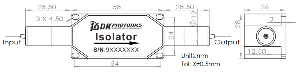
*Due to ongoing design improvements, the package size is subject to change. Please contact DK Photonics for confirmation.
When you inquire, please provide the correct P/N number according to our ordering information, and attach the appropriate description would be better. If need any connector, we do not recommend choosing a 250μm bare fiber pigtail. For high power applications, we recommend direct splicing without connectors.
| ① | ② | ③ | ④ | ⑤ | ⑥ |
| Wavelength | Optical Power | Power Type | Fiber Type | Pigtails Diameter | Fiber Length |
| 30:1030nm
40:1040nm 53:1053nm 64:1064nm 80:1080nm XX: Other |
10:10W
20:20W 30:30W XX: Other |
P: Pulsed
C: Continuous Wave |
XXX: fiber code | 25: bare fiber
90:900μm Loose Fiber XX: Others |
08:0.8m
10:1.0m XX: Other |
Part Number Example: HPPII-64-20-P-20/130/08D-25-08
Description: 1064nm High Power Polarization Independent Isolator – 20W, pulsed power type, 20/130um, NA0.08/0.46 fiber, with bare fiber & 0.8m length.
If you need to customize other specifications, please provide detailed description for your requirement.
Function
An optical isolator is a passive magneto-optic device that only allows light to travel in one direction. Isolators are used to protect a source from back reflections or signals that may occur after the isolator. Back reflections can damage a laser source or cause it to mode hop, amplitude modulate, or frequency shift. In high-power applications, back reflections can cause instabilities and power spikes.
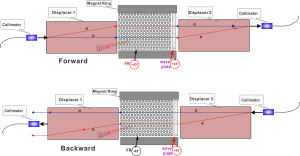
An isolator’s function is based on the Faraday Effect. In 1842, Michael Faraday discovered that the plane of polarized light rotates while transmitting through glass (or other materials) that is exposed to a magnetic field. The direction of rotation is dependent on the direction of the magnetic field and not on the direction of light propagation; thus, the rotation is non-reciprocal. The amount of rotation β equals V x B x d, where V, B, and d are as defined below.
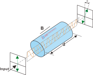
Figure 1.Schematic diagram of Faraday effect
Faraday Rotation
β = V x B x d


 DownloadDatasheet in PDF