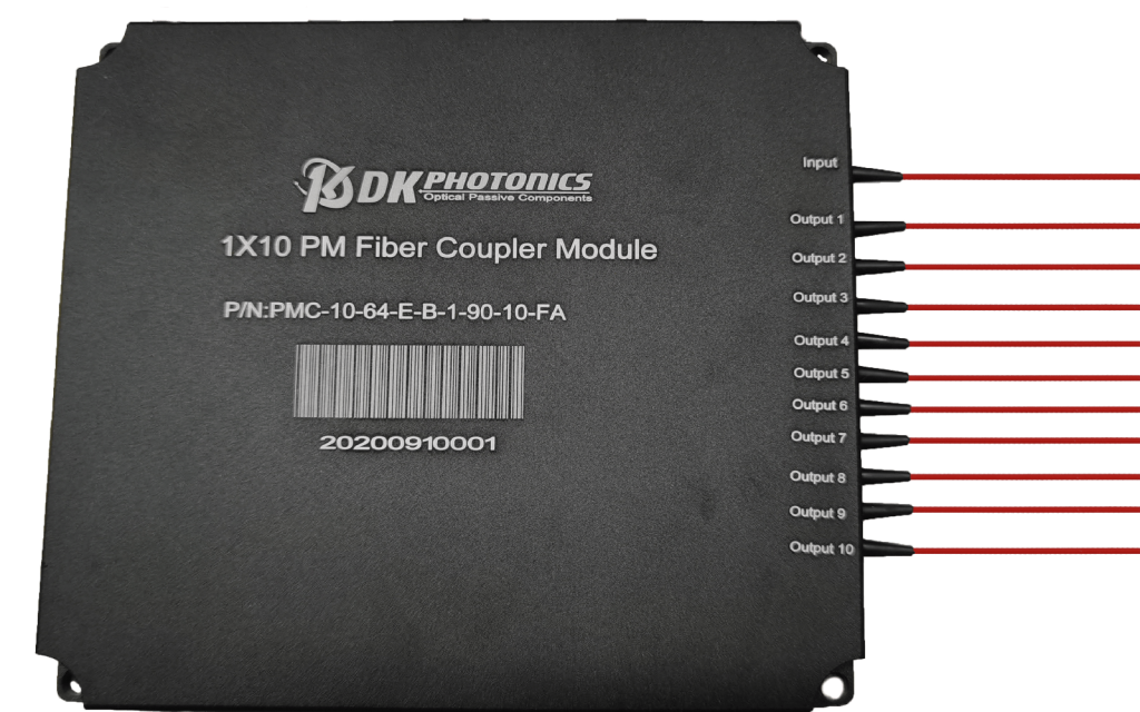
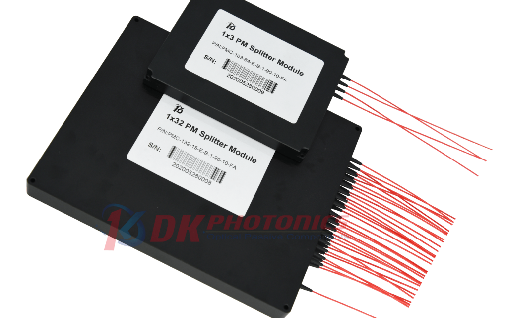
Polarization maintaining splitter/coupler modules combine multiple incoming optical fiber inputs into one output, while maintaining the polarization state of the light. It can also be used as a PM splitter.
Our PM coupler modules are assembled using thin-film filter-based or FBT fused 1×2 and 2×2 PM optical fiber couplers.The Polarization Maintaining Coupler is available in a wide range of coupling ratio. PM couplers are widely used in fiber optic communication systems, Raman Amplifiers and other fiber instrument applications.
If you do not see a standard PM fiber Coupler Module that meets your needs, we welcome the opportunity to review your desired specification and quote a custom PM Fiber Coupler Module. Requests for custom fiber pigtails, different coupling ratio different wavelengths and handling power of operation or other specific needs will be readily addressed.
Performance Specifications
| PARAMETER |
UNIT |
VALUES |
| Center Wavelength |
nm |
1310 |
| Type |
– |
1X4 |
1X8 |
| Operating Wavelength Range |
nm |
± 30 |
| Typ. Insertion Loss |
dB |
7.5 |
11.0 |
| Insertion loss |
dB |
≤8.0 |
≤11.5 |
| Uniformity |
dB |
≤0.8 |
≤1.0 |
| Directivity |
dB |
≥50 |
≥45 |
| Extinction ratio Type B |
dB |
≥20 |
≥18 |
| Extinction ratio Type F |
dB |
≥22 |
≥20 |
| Return loss (input/output) |
dB |
≥50 |
| Fiber Type |
– |
PM1300 |
| Operating temperature |
℃ |
-5 ~ + 70 |
| Storage temperature |
℃ |
-40 ~ + 85 |
| Max. Optical Power |
W |
0.5, 2, 5, 10 |
| Dimensions |
mm |
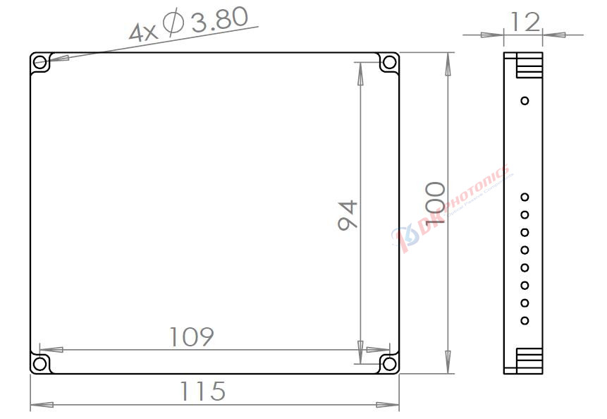
115x100x12(Aluminum) |
| “B” for Both axis working, “F” for Fast axis blocking |
1. Above specifications are for device without connector. All parameters are tested at room temperature.
2. Other split ratios and structures can also be customized according to requirements.
3. If tap port coupling ratio is ≤ 5%, ER will be 2dB lower; for ≤1% tap port, ER is out of concern.
4. For devices with connectors, IL will be 0.3dB higher, RL will be 5dB lower and ER will be 2dB lower. The default connector key is aligned to slow axis. Power transmits through the connector less than 2W.
5. If there is pulse application, please be sure to inform us of pulse energy and peak power.


 DownloadDatasheet in PDF
