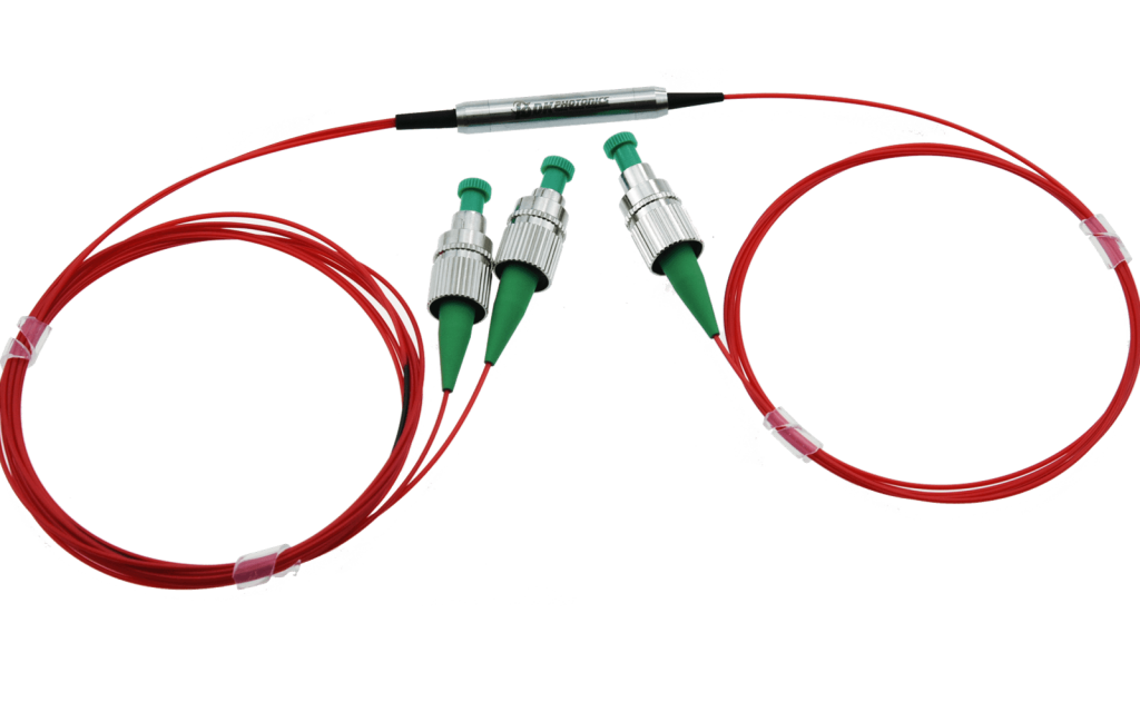
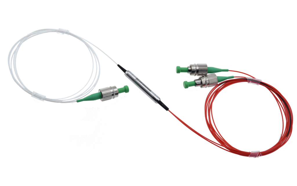
| Polarization Beam Combiner:
Routing path is from port 1, 2 to 3, Here are three options of polarized state from Port 1, 2 to Port 3 |
| Option 1:PM to SM fiber |
Port 1: 50%, Linear polarized light in, through slow axis,
Port 2: 50%, Linear polarized light in, through slow axis
Port 3, 100%, Circularly polarized light Out, |
| Option 2: PM to PM fiber, port 1 is slow axis 0° aligned to port 3 |
Port 1, 2, only work through slow axis, blocked the fast,
The slow axis of port 1 is aligned to the slow axis of port 3,
The slow axis of port 2 is aligned to the fast axis of port 3, |
| Option 3:PM to PM, port 1 is slow axis 45° aligned to port 3 |
Port 1, 2, only work through slow axis, blocked the fast,
Port 1 or 2, 100%, Linear polarized light in, through slow axis,
Port 3, 25% linear polarized light out, through slow axis, and 25% by the fast, |
| Polarization Beam Splitter:
Routing path is from port 3 to 1,2, Here are three options of polarized state from Port 3 to Port 1 & 2 |
| Option 1: SM to PM fiber |
Port 3, Circularly polarized light in,
Port 1: 50%, Linear polarized light out, through slow axis,
Port 2: 50%, Linear polarized light out, through slow axis |
| Option 2: PM to PM, port 3 is slow axis 0° aligned to port 1 |
1. Port 3, Linearly polarized light in, through slow axis,
Port 1: 100%, Linear polarized light out, through slow axis, Port 2: 0%
2. Port 3, Linearly polarized light in, through fast axis,
Port 1: 0%, Port 2: 100%, Linear polarized light out, through slow axis |
| Option 3: PM to PM, port 3 is slow axis 45° aligned to port 1 |
1. Port 3, Linearly polarized light in, through slow axis,
Port 1: 50%, Linear polarized light out, through slow axis, Port 2: 50%, Linear polarized light out, through slow axis
2. Port 3, Linearly polarized light in, through fast axis,
Port 1: 50%, Linear polarized light out, through slow axis, Port 2: 50%, Linear polarized light out, through slow axis |


 DownloadDatasheet in PDF


