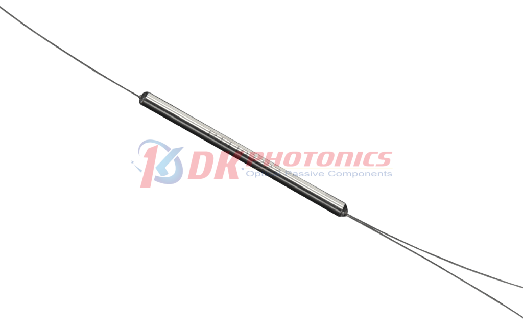
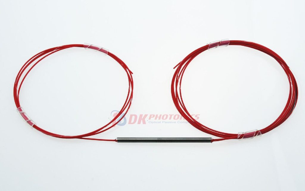
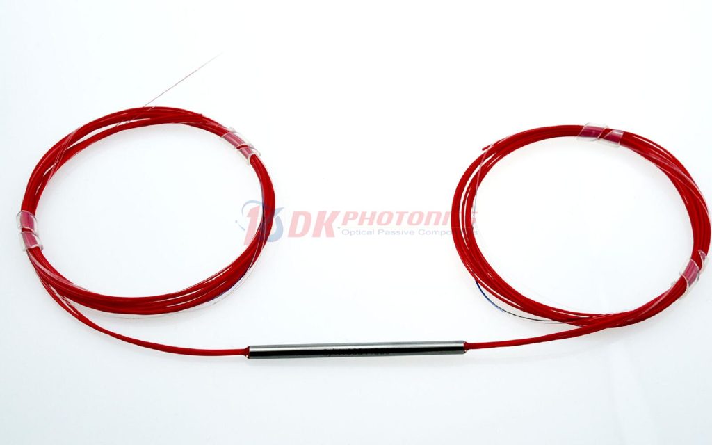
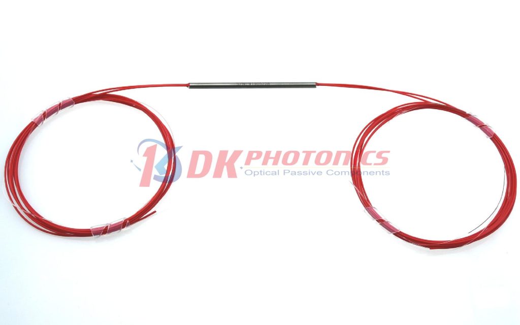
DK Photonics uses unique fusing technique to build the 400~750nm PM fiber fused coupler. The coupling ratio could be selected according to customer’s request. It features low excess loss, small size and high polarization extinction ratio.
If you do not see a standard PM Fused Coupler that meets your needs, we welcome the opportunity to review your desired specification and quote a custom PM fused Coupler. Requests for custom fiber pigtails, different wavelengths, tap Ratio and handling power of operation or other specific needs will be readily addressed.
Performance Specifications
| PARAMETER |
UNIT |
VALUES |
| Configuration |
– |
1×2 or 2×2 |
| Center Wavelength |
nm |
450, 488 |
| Wavelength Range |
nm |
±10 |
| Coupling Ratio |
% |
1~50 |
| Typ. Excess Loss |
dB |
2.0 |
| Min. PER |
dB |
18 |
| Min. Return Loss |
dB |
55 |
| Max. Power Handling |
mW |
50 mW (With Connectors or Bare Fiber),100 mW (Spliced) |
| Max. Tensile Load |
N |
5 |
| Fiber Type |
– |
PM460-HP |
| Operating Temperature |
℃ |
-10 ~ +75 |
| Storage Temperature |
℃ |
-40 ~ +85 |
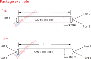
| Dimensions (Ф×L) |
mm |
Ф3.0×54, or Ф3.0×60 |
- Above specifications are for device without connector, and the PM fused coupler is both axis working, no axis can be blocked; default test extinction ratio is on the slow axis. All parameters are tested at room temperature at central wavelength only.
- ER data listed in the table are for the ports with coupling ratio greater than 10%. It will be 2 dB lower for a tap port with coupling ratio between 5-10%. For <5% tap port, ER is not considered if there is no requirement.
- For devices with connectors, IL will be 1.5dB higher, RL will be 5dB lower and ER will be 2dB lower. The default connector key is aligned to slow axis.
Package Dimension
Order information
P/N: PMFBTC-①-②-③-④-⑤-⑥-⑦
When you inquire, please provide the correct P/N number according to our ordering information and attach the appropriate description would be better. If need any connector, we do not recommend choosing a 250μm bare fiber pigtail.
|
①
|
②
|
③
|
④
|
⑤
|
⑥
|
⑦
|
|
Port
|
Operating Wavelength
|
Coupling Ratio
|
Fiber type
|
Pigtail Diameter
|
Fiber Length
|
Connector
|
|
102:1×2
202:2×2
|
488:488nm
XX: Others
|
50:50/50
40:40/60
20:20/80
10:10/90
|
05:5/95
01:1/99
XX: Others
|
XXX: fiber name
|
25:250μm bare fiber
90:900μm Loose tube
XX: Others
|
08:0.8m
10:1.0m
XX: Others
|
00: None
FP: FC/PC
FA: FC/APC
XX: Others
|
Part Number Example: PMFBTC-102-488-50-P46-25-10-00
Description: 488nm 1×2 PM Fiber Fused Coupler, 50mW, 50:50 coupling ratio, 1.0m PM460-HP bare fiber, and no connector at all ports.
Ordering Information for Custom Parts:
If you need to customize other specifications, please provide detailed description for your requirement.

 DownloadDatasheet in PDF
