Fiber Optic Current Transducer Applications
As the power industry continues to develop toward high voltage and large capacity, the traditional electromagnetic current transformer based on electromagnetic induction principle exposes more and more problems. For example, its own measurement mechanism determines the transformer in high voltage and super There is difficulty in insulation under high pressure, easy to explode, limited measurement range and accuracy, and easy to saturate under system failure conditions. The rapid development of optoelectronics and fiber optic communication in recent years has promoted the research and application of the new Fiber Optic Current Transducer (FOCT).
The FOCT is based on the Faraday magneto-optical effect, and the magnitude of the current is determined by measuring the angle at which the polarization plane rotates due to the action of the magnetic field generated by the current when passing through the magneto-optical material. Compared with traditional electromagnetic current transformers, FOCT has many advantages, including small size, simple insulation structure, no safety hazards, no magnetic saturation, high measurement bandwidth and precision, and anti-electromagnetic interference. It can adapt to the working voltage of transmission network. Increasing demands also meet the need for high precision, high range and safety.
Working principle:
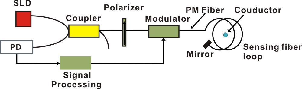
Figure 1: Schematic diagram of Fiber Optic Current Transducer
The working principle of FOCT is as shown in the figure below. The light emitted from the broadband source is linearly polarized after passing through the polarizer, and the linearly polarized light is injected into the polarization-maintaining fiber at 45 degrees to propagate forward along the fast axis or the slow axis, respectively. After the two orthogonal modes pass through the 1/4 wave plate, they become left-handed and right-handed circularly polarized light respectively enter the sensing fiber ring, and are subjected to the magnetic field generated by the current in the conductor, and the left and right circularly polarized light propagates at different speeds, causing the phase of the light wave. The change. After the specular reflection of the light at the end of the sensor, the polarization modes of the two circularly polarized ends are interchanged, and the magnetic field is again subjected to the magnetic field by the sensing fiber to double the effect. After the two circularly polarized lights pass through the wave plate, they return to linearly polarized light, and interfere at the polarizer, and measure the interference light intensity to detect the phase difference, thereby obtaining the magnitude of the measured current.
Required device:
- SLD (SuperLuminescent Diode): super luminescent LED light source;
- PIN: Photodetector;
- Coupler: fiber coupler;
- Polarizer: in-line fiber polarizer;
- Modulator: phase modulator;
- PM Fiber: polarization-maintaining fiber;
- QWP (Quarter Wave Plater): 1/4 wave plate;
- Mirror: mirror;
- Sensing Fiber Loop: sensing fiber ring, common communication fiber;
- Conductor: Current carrying conductor.
DK Photonics offers a variety of passive components with compact package for building Fiber Optic Current Transducer systems. Contact DK Photonics regarding your requirements.
Click here to download the PDF file: 