
980/1064nm Wavelength Division Multiplexers (WDMs) are used to combine or split two different single mode signals with low insertion loss. DK Photonics' WDMs featured on this page are manufactured using Fused Biconic Taper (FBT) technology and are designed for common NIR and telecom wavelengths. They are an ideal solution for combining pump and signal wavelengths in fiber lasers and amplifiers or for combining telecom signals.
|
Parameter |
Unit |
Vaules |
|
Operating wavelength |
nm |
980 /1064 or 980 /1053 |
|
Operating bandwidth |
nm |
±5 |
|
Insertion loss |
dB |
≤0.40 |
|
Isolation |
dB |
≥15 |
|
PDL |
dB |
≤0.10 |
|
Return Loss |
dB |
≥55 |
|
Fiber Type |
- |
1060-XP or other |
|
Maximum Power Handling |
W |
1, 2, 5, 10 |
|
Operating temperature |
℃ |
-40 ~ +85 |
|
Storage Temperature |
℃ |
-50 ~ +85 |
|
Port Configuration |
- |
1x2/2x2 |
|
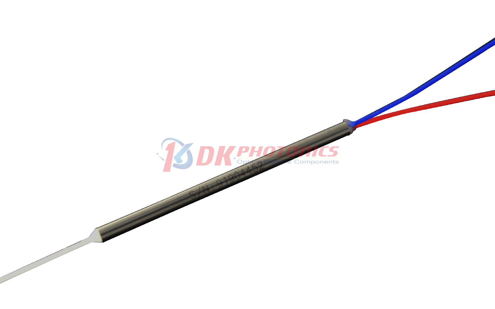
Package Dimension |
mm |
Ф3.0×54(bare fiber), or Ф3.0×60(900μm loose tube) |
|
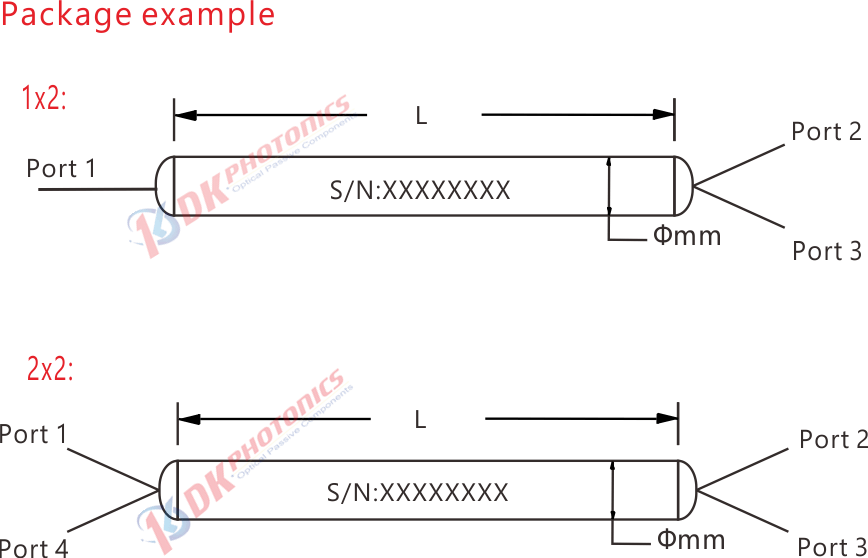
①
|
②
|
③
|
④
|
⑤
|
⑥
|
|
Port
|
Wavelength
|
Handling Power
|
Pigtails Diameter
|
Fiber Length
|
Connector
|
|
102:1x2
202:2x2
|
9864:980/1064nm
9853:980/1053nm
XX: Others
|
L: <1W
2:2W
5:5W
10:10W
X: Other
|
25:250μm
90:900μm
XX: Others
|
05:0.5m
10:1.0m
15:1.5m
XX: Others
|
00: None
FP: FC/PC
FA: FC/APC
SA: SC/APC
LA: LC/APC
XX: Others
|
Description: 1x2 single mode 980/1064 WDM, 2W, 1060-XP fiber, bare fiber, 1.0m length fiber pigtails, without connectors at all ports.
If you need to customize other specifications, please provide detailed description for your requirement.
1. Function
WDM(Wavelength Division Multiplexin ) is the optical passive device, it can coupling two or more different wavelengths of light into the same optical fiber transmission. It can also be a plurality of different wavelengths of light in the same optical fiber were separated into different optical fiber transmission.
2. Characteristic
1). To combine or separate two (usually two) or more beams of light of different wavelengths.
2.) Wide operating bandwidth, low insertion loss, high channel isolation, high stability and reliability.
3). Manufactured with fused tapered technology, multiple wavelength combinations are available in the wavelength range of 450 nm-2050 nm.
3. Description
1). Fused taper structure WDM
Let’s take the FBT Coupler case, we default that there is only one energy transfer from one core to another. In fact, in the coupling region (also known as the interaction length), energy is transmitted back and forth between two fibers many times. This transmission rate is a function of wavelength, so if the wavelength used is different from the design wavelength, the energy transfer ratio (or coupling ratio) will be different.
For example, let's assume that two different wavelengths of light (red and blue) input from port 2 and port 3:
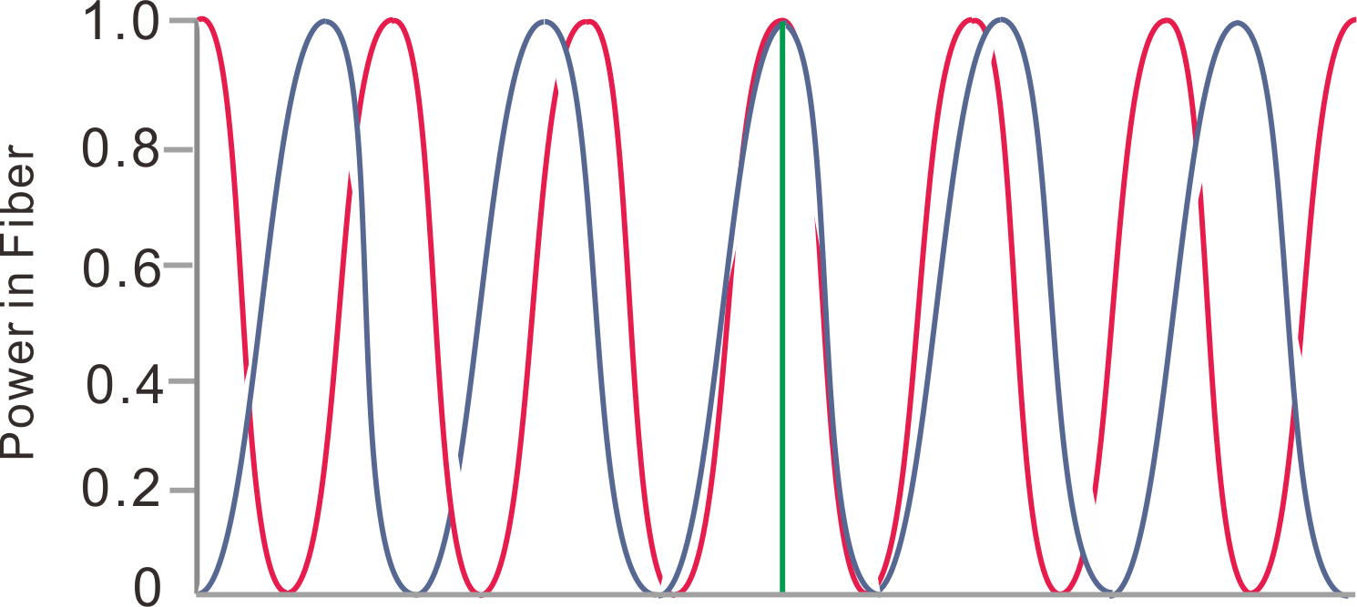
Figure 1. Curve of red and blue light energy output from port 1 with coupling length.
The energy transfer of the two wavelengths is shown in Figure 1. The horizontal axis is the length of the coupling region and the vertical axis is the output light energy of port 1. As shown in the figure, when we control the length of the coupling region to L, red light and blue light are input at the two input terminals respectively, and the output energy of the two lights at port 1 is 100%, that is to say, the light of different wavelengths input from ports 2 and 3 converge at the output of port 1.
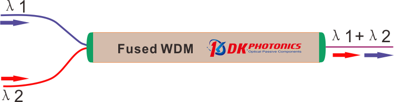
Figure 2. Schematic diagram of WDM MUX wavelengths.
Similarly, according to the principle of reciprocity of tapered devices and in combination with figure 2, when we input red light and blue light reversely from port 1, the red light and blue light will be output from two "input" terminals 2 and 3 respectively. Wavelength division multiplexing optical transmission principle of fused biconical devices: combination and separation of light with different wavelengths.
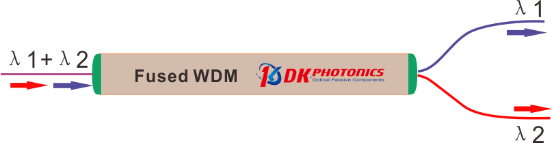
Figure 3. Schematic diagram of WDM DEMUX wavelengths.
Therefore, as long as we control the coupling length L and the spacing d between the two cores in the manufacturing process, the wavelength division multiplexing device we want can be prepared by melting taper technology.
4). The main parameters
a. IL (Insertion Loss)
The ratio of the input loss to the output loss of the passive device is defined as the additional power generated by the insertion port of the passive device:
![]()
As shown in the formula above, Pin is the power of the inverted input, Pout is the power of the inverted output. The performance of the device requires the insertion loss of forward incident light to be as small as possible (Note: Generally, the calculation result is negative, but the negative sign is often omitted in actual filling or use, the same as below.).
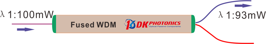
Figure 4.WDM schematic diagram of insertion loss test of output port 1.
As show in the Figure 4,we can see that the input port input red light power Pin =100 mW, input blue light power of Output 1 port Pout=93 mW, so the insertion loss of Output 1 is:
IL= 10 × log (100/93)
= 10 × 0.032
= -0.32 dB
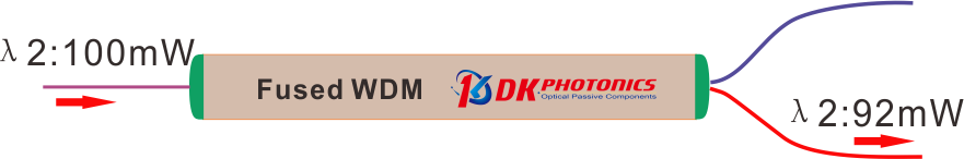
Figure 5. WDM schematic diagram of insertion loss test of output port 2.
As show in the Figure 5,we can see that the input port input red light power Pin =100 mW, input red light power of Output 2 port Pout=92 mW, so the insertion loss of Output 1 is:
IL= 10 × log (100/93)
= 10 × 0.036
= -0.36 dB
b. Channel ISO (Isolation)
Isolation refers to the ability of one optical path of WDM to isolate the light in other optical paths. Each port of the coupler is designed to have low insertion loss (i.e., high transmission) at the desired wavelength while suppressing the signal at the specified wavelength of the other port, which minimizes cross talk between the ports. Therefore, isolation is specified as the insertion loss of these undesired wavelengths. High dB values of isolation are ideal for signal separation applications using a WDM.
![]()
Pin is the optical power of optical input, Pout is the optical power of not expected channel optical output.
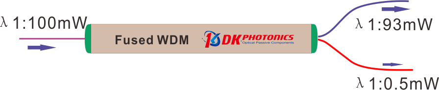
Figure 6.WDM schematic diagram of isolation loss test of output port 1.
As show in the Figure 6, Output 1 is blue light transmission channel, Output 2 red light transmission channel. Theoretically, all the blue light input from the input port should output from Output 1, but the WDM cannot completely isolate the blue light output to Output 2. Therefore, in order to show the isolation ability of WDM devices to not expected channel light, the concept of channel isolation is introduced.
As show in the Figure 6, light Input optical power of blue light Pin =100 mW, and the output power of Output 2 Pout=0.5 mW, so the ISO of Output 2 is:
ISO= 10 × log (100/0.5)
= 10 × 2.30
= 23.0dB
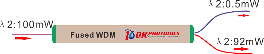
Figure 7. WDM schematic diagram of isolation loss test of output port 2.
As show in the Figure 7, Input optical power of red light Pin =100 mW, and the power of the Output 1 Pout=0.5 mW, so ISO of Output 1:
ISO= 10 × log (100/0.5)
= 10 × 2.30
= 23.0dB
 DownloadDatasheet in PDF